


AOE (Enterprise-Grade Network Communication Equipment)
AOE
A Technical Overview of Antenna Design
Antenna design for enterprise network equipment is a systems engineering task requiring multi-objective trade-offs across spectrum planning, mechanical form factors, arraying/combining, front-end linearity, environmental robustness, and regulatory compliance. By defining frequency, throughput, and coverage targets early; choosing manufacturable structures and processes; enforcing a layered test strategy from passive to active and from lab to field; and prioritizing isolation, filtering, phase consistency, and environmental reliability, products can achieve superior coverage quality, capacity, and stability in complex enterprise scenarios while reducing mass-production and certification risks and accelerating time-to-market. Provide your specific form factor, port count, target spectra, and installation environment to receive a tailored antenna topology and test matrix.
Key Application Scenarios
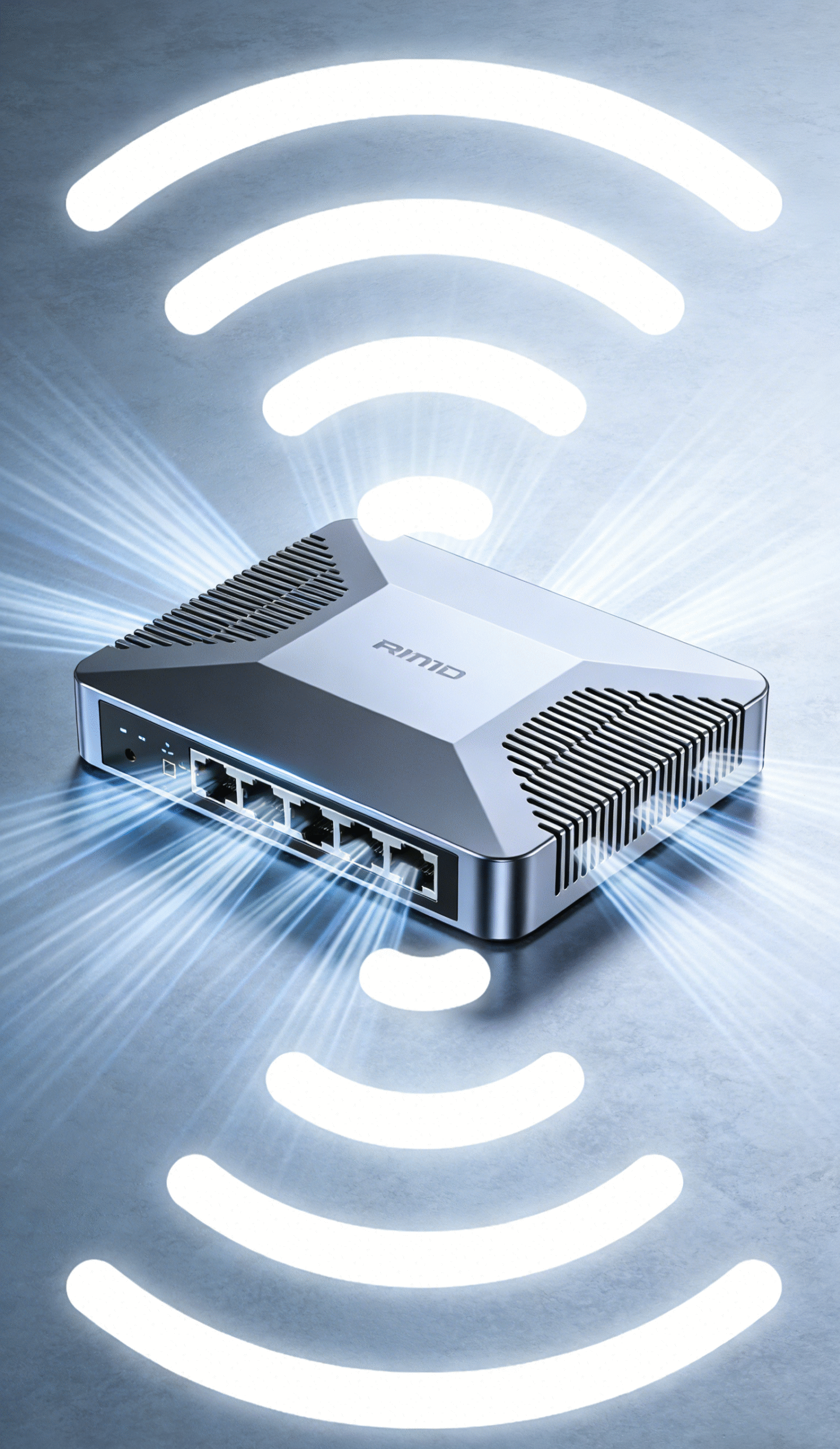
enterprise gateways
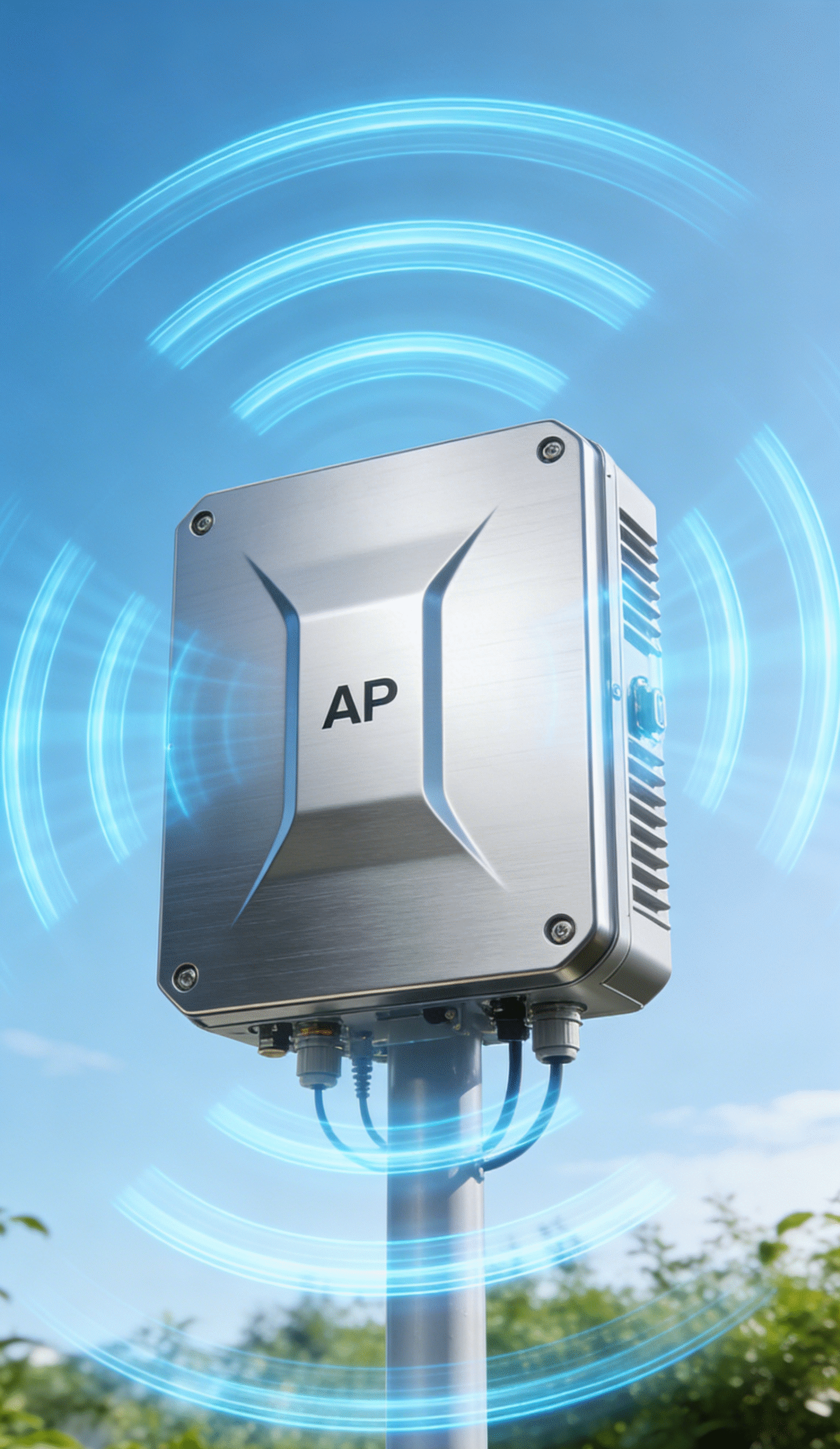
Indoor/outdoor APs, 5G CPE/routers
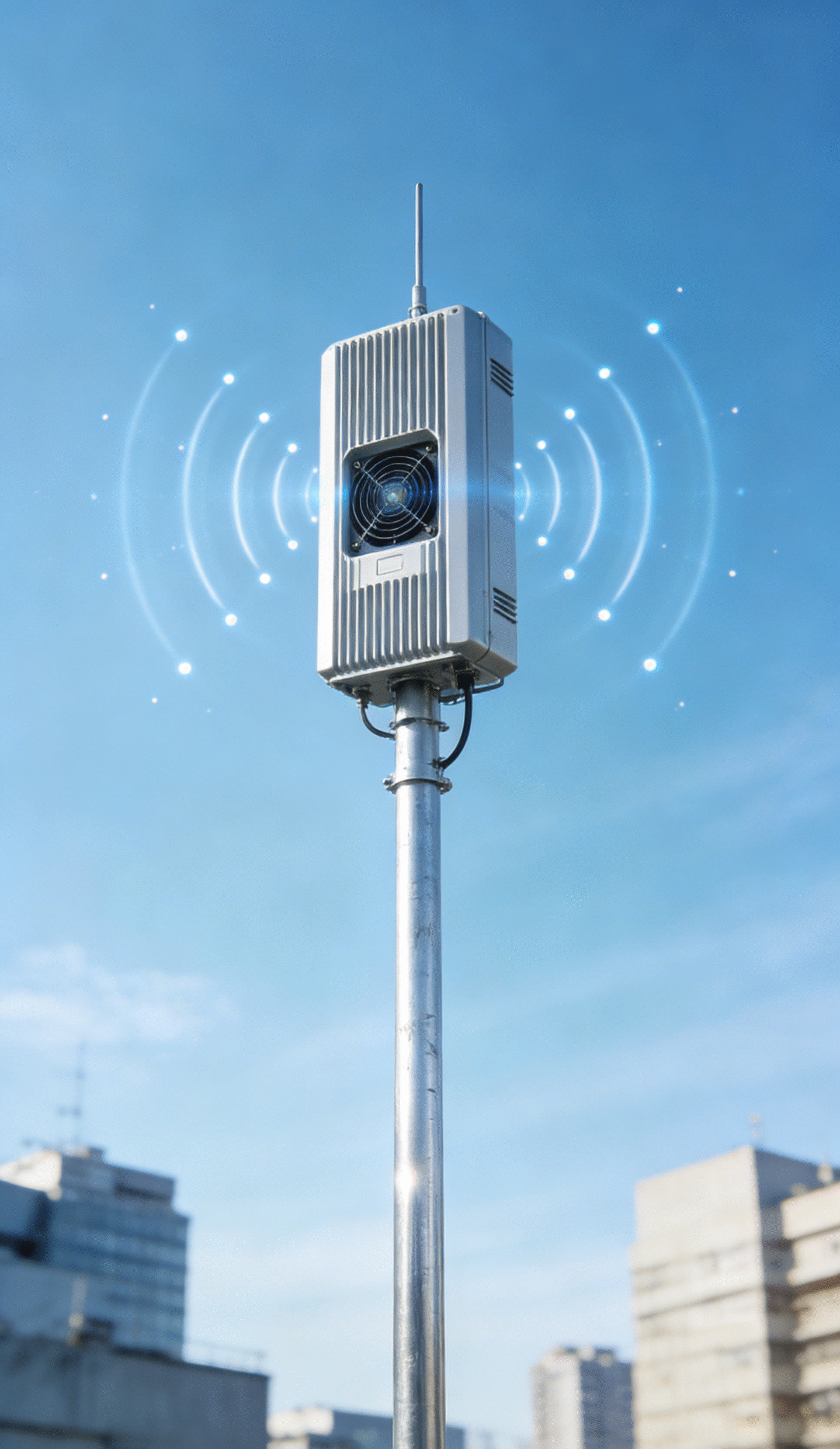
Private network gNodeB/small cells
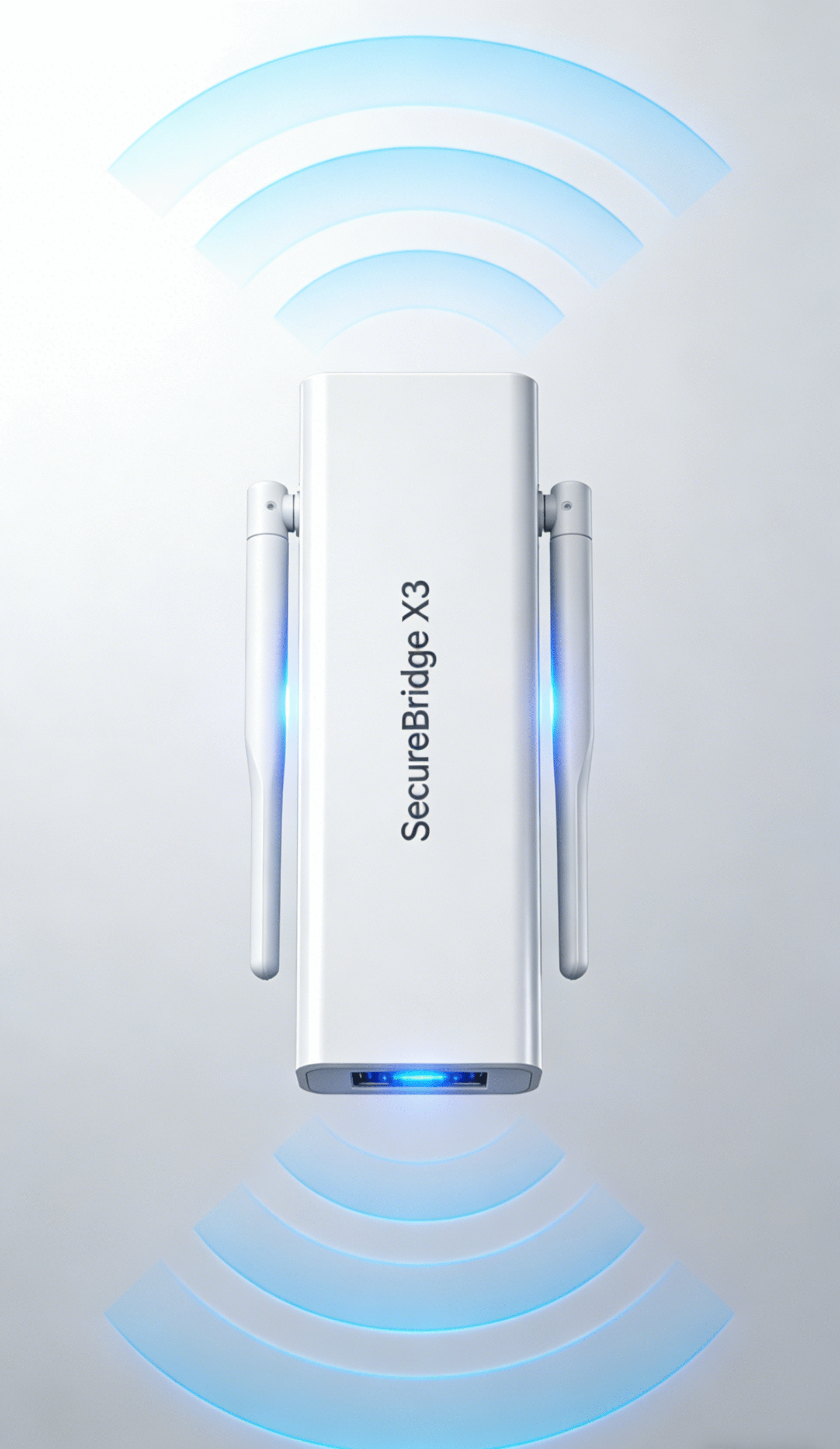
Bridging for security
1. Spectrum Overview
Antenna design must support multi-standard, multi-band concurrency with goals of high concurrency, high throughput, low latency, strong robustness, and high reliability.
Cellular and Private Networks
-
- 4G LTE: 700/800/900/1800/2100/2600 MHz; e.g., B3/B7/B20/B28/B38/B40/B41
- 5G NR Sub-6G: n1/n3/n7/n28/n41/n77/n78 (approximately 1.8–2.7 GHz and 3.3–3.8/4.1–4.9 GHz)
- 5G mmWave (optional): n257/n258/n261 (26/28/39 GHz) for campus high-density hotspots and backhaul
- Industry/private: 450 MHz, 1.4/1.8/3.5 GHz private bands; hybrid public-private deployments
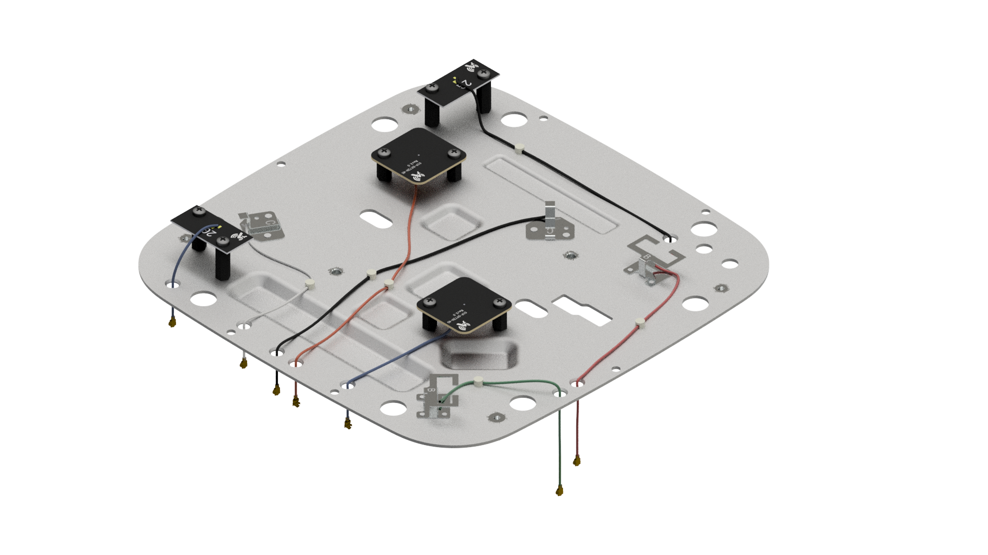
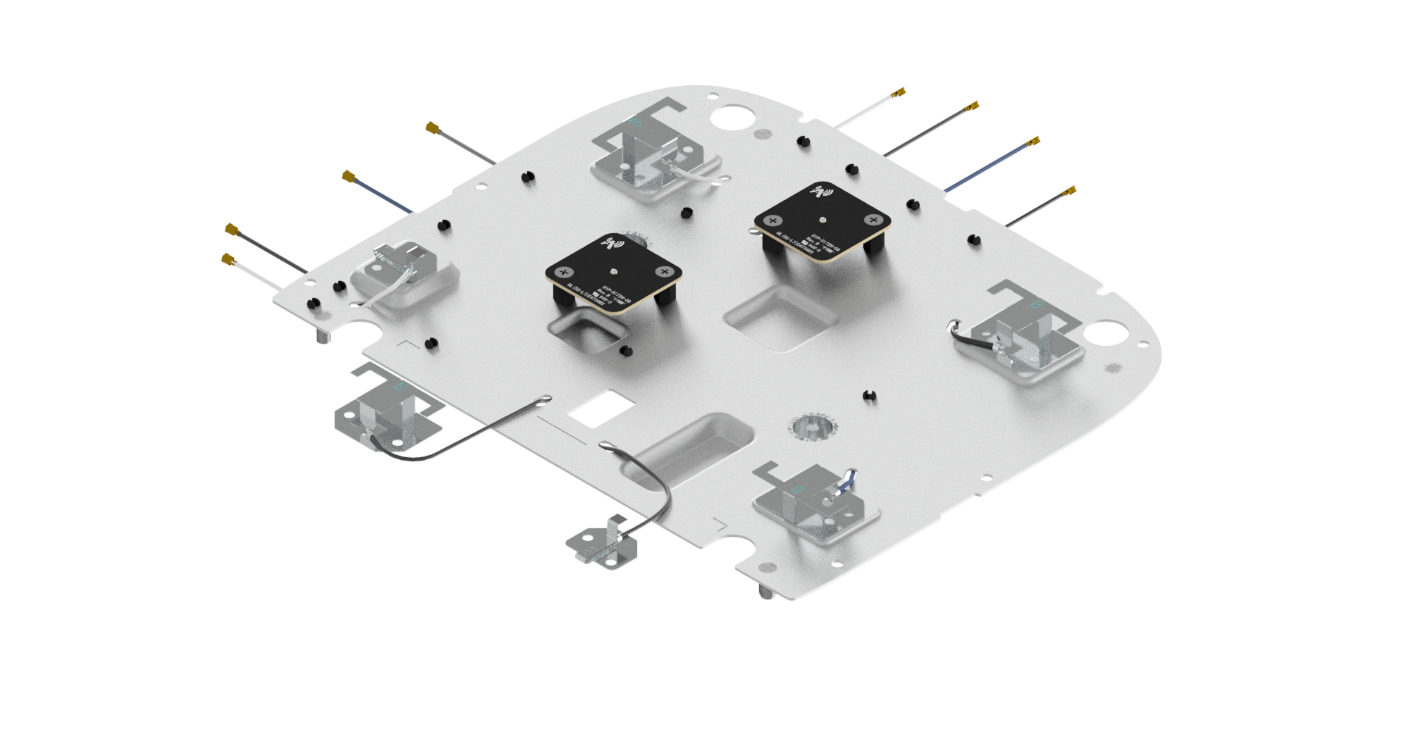
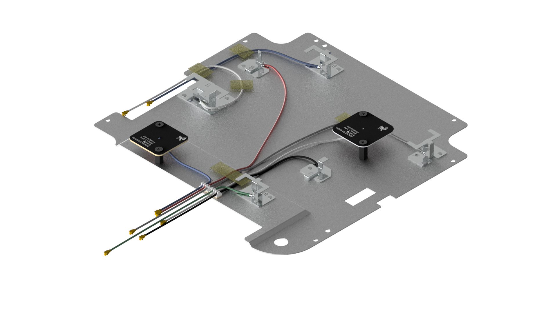
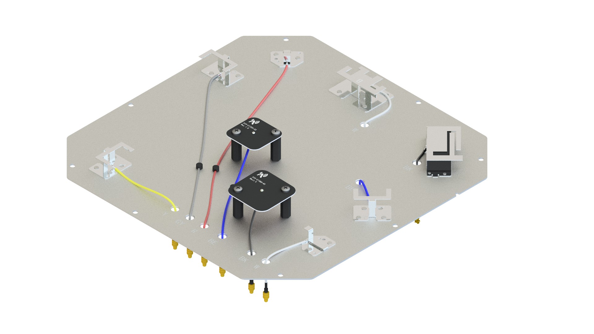
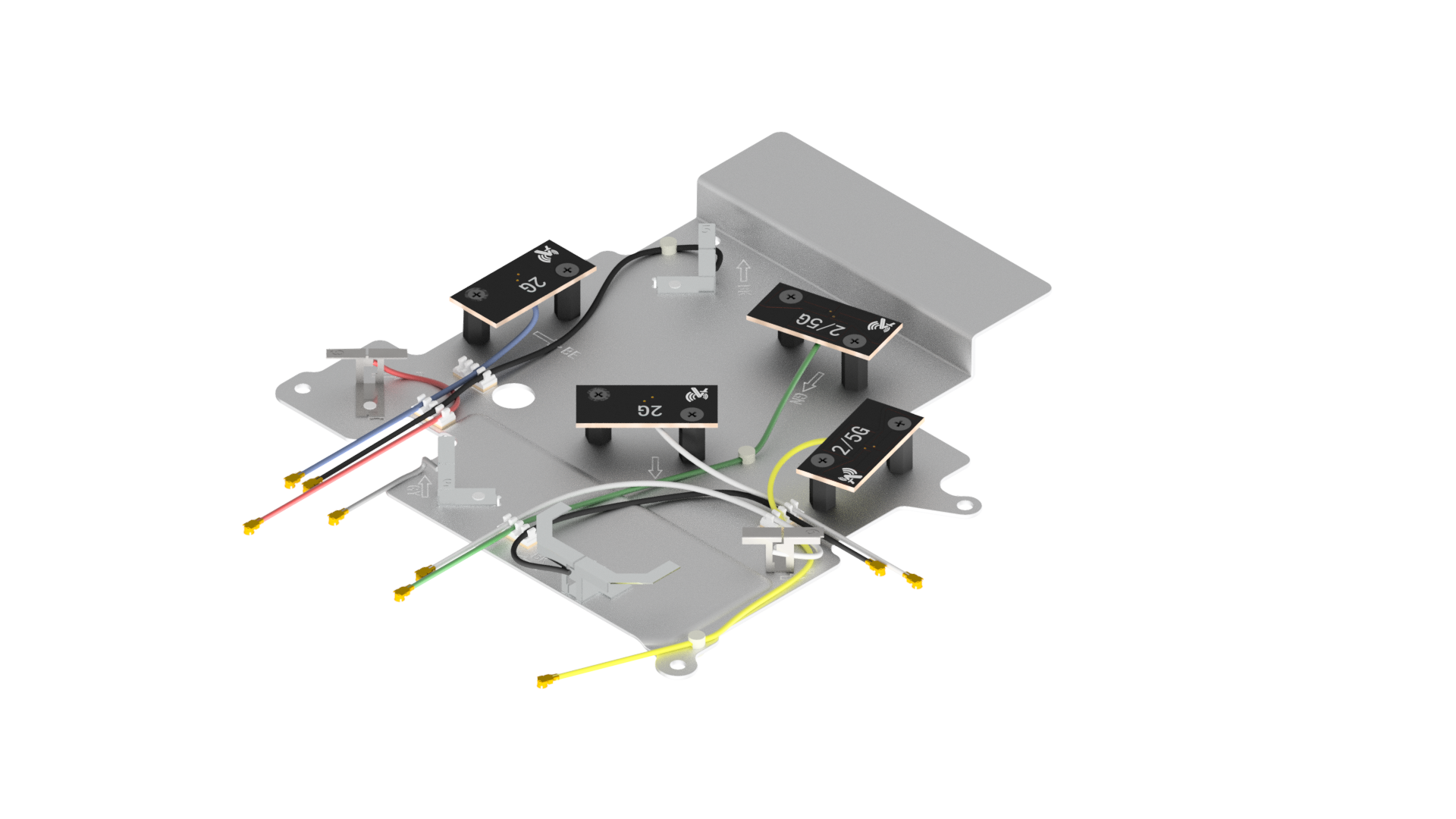
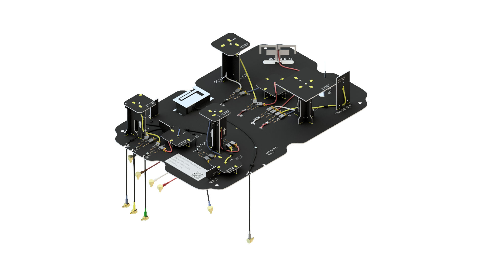
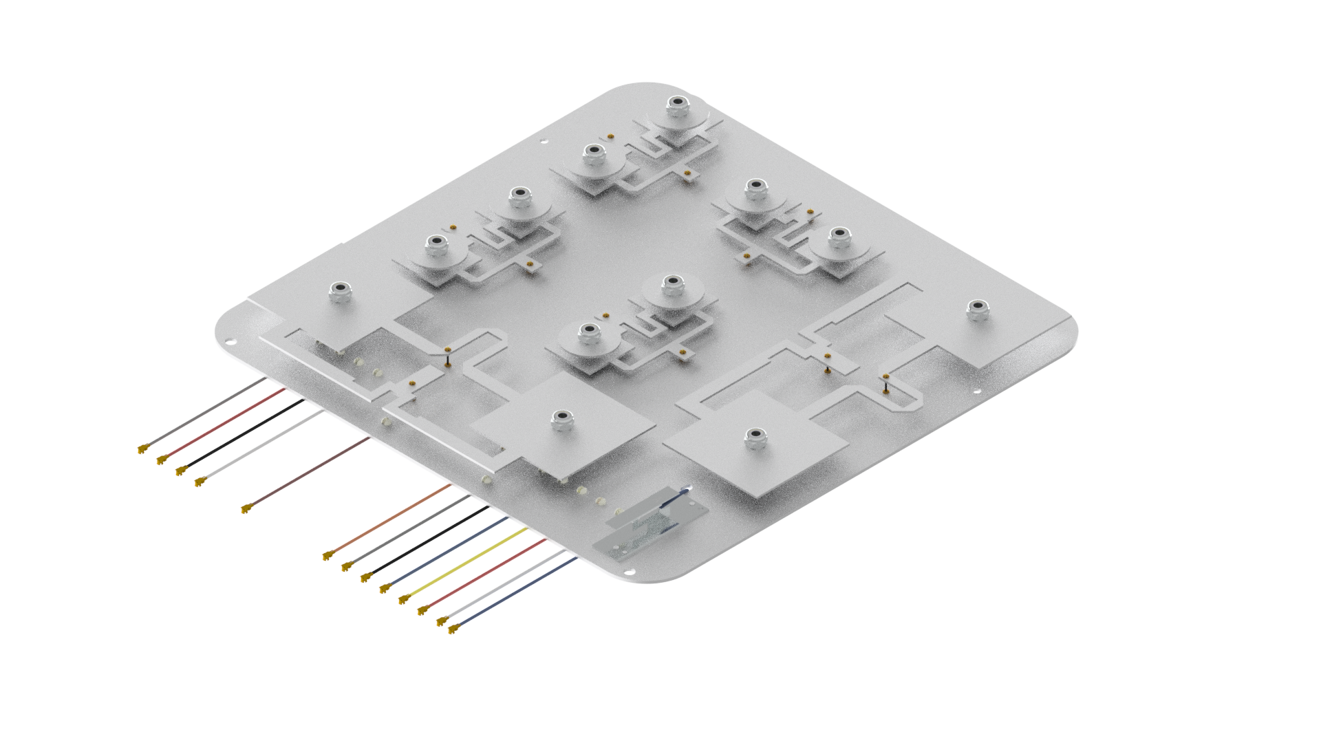
2. Antenna Form Factors and Integration
Enterprise devices typically adopt a hybrid of internal and external antennas to balance industrial design, RF performance, and serviceability.
Embedded
-
- PIFA/IFA/multi-branch inverted-F: suited for 2.4/5/6 GHz and multi-band cellular; compatible with plastic enclosures
- FPC antennas: conformal to housings, easing multi-port MIMO placement and rapid tuning
- LDS/LDP antennas: multi-band/multi-polarization on complex 3D surfaces for improved volume utilization
- Microstrip/patch/slot: used in directional panels or ceiling AP arrays, enabling beamforming
3. Antenna Design Requirements
Electrical, Mechanical, and System-Level
Bands and Bandwidth
-
- Cover target regional spectra; Wi‑Fi 6E/7 requires the complete low/mid/high 6 GHz sub-bands. Cellular must satisfy CA and harmonic/intermod constraints.
- Provide sufficient operational bandwidth and thermal drift margin; compensate resonance shifts from metallization, wall proximity, and user proximity.
Radiation Performance
-
- Gain and patterns: indoor APs emphasize uniform azimuth coverage and controlled downtilt; outdoor APs/CPE balance azimuthal omni with compressed vertical HPBW; backhaul requires narrow beams and low sidelobes.
- Efficiency: embedded antennas in typical installation should achieve ≥40–60% at 2.4/5/6 GHz; external directional panels ≥60–80%.
- Polarization: linear for Wi‑Fi/cellular; dual/cross-polar arrays to improve multipath resilience and throughput in complex scenarios; GNSS requires RHCP with controlled axial ratio.
Matching and Isolation
-
- VSWR/return loss: ≤2.0 typical, ≤1.8 on critical sub-bands; maintain stability over temperature, humidity, and assembly tolerances.
- Port isolation: ≥15–20 dB for same-standard MIMO ports; ≥25–30 dB for heterogeneous (cellular/Wi‑Fi/GNSS) coexistence to mitigate interference and noise coupling.
- Correlation/ECC: keep ECC <0.2/0.1 for MIMO diversity and capacity.
Combining and Filtering Architecture
-
- Diplexers/combiners and out-of-band filtering for multi-standard coexistence, balancing insertion loss and linearity.
- Front-end dynamic range and intermodulation robustness (IP3/IP2) against strong nearby interferers (5G macro, microwave backhaul, EV charger EMI).
Active Front-End and RF Path
-
- PA/LNA placement: minimize path length from PA to antenna and antenna to LNA to reduce feedline loss, improving EIRP and G/T.
- Phase consistency: control per-chain phase/amplitude for beamforming; unify cable/connector specs.
- ESD: provide IEC 61000‑4‑2 compliant ESD protection at antenna ports and exposed metal while accounting for parasitics in matching.
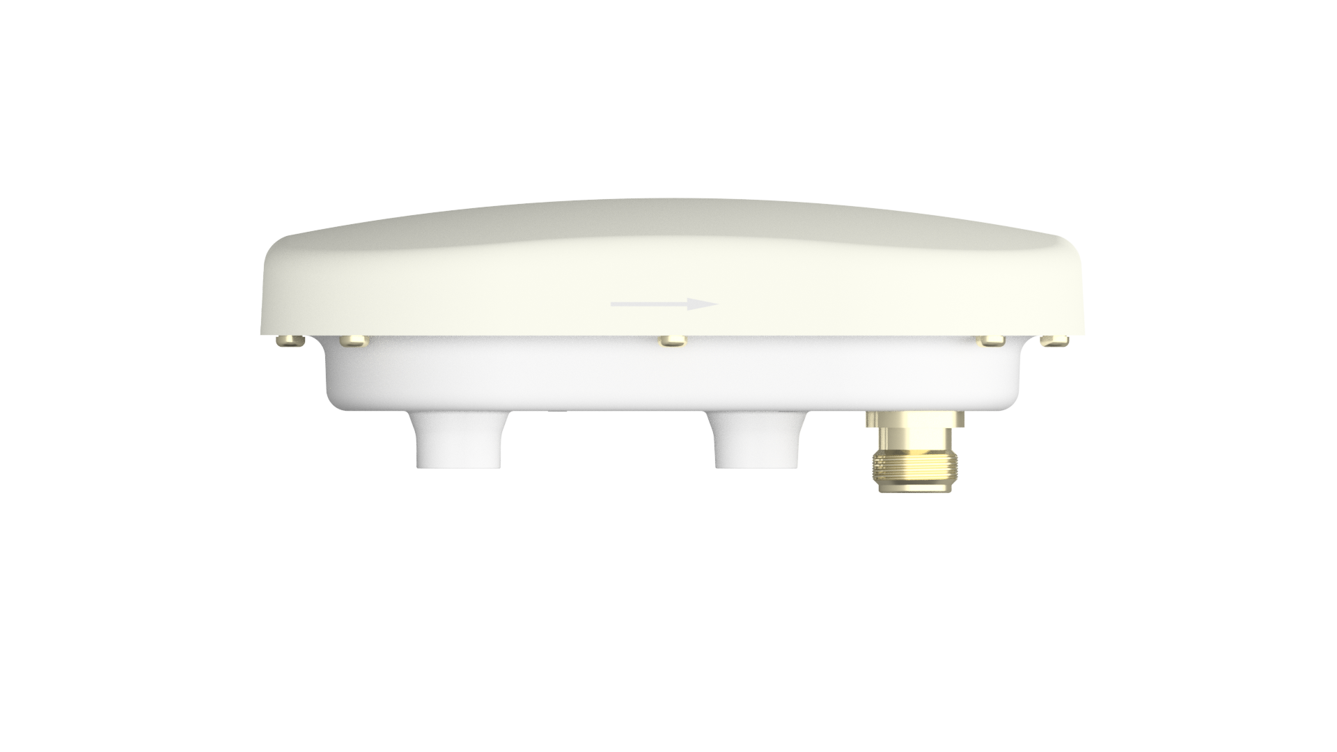
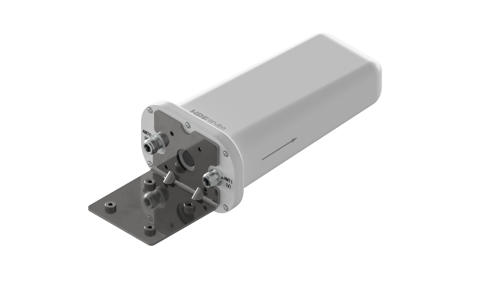
Mechanical and Environmental
-
- Control enclosure dielectric Dk/Df; isolate antennas from metal frames/heat sinks and ensure robust grounding.
- Ingress protection: IP65/IP67 for outdoor, resistance to salt fog and UV; wind load and vibration reinforcement.
- Mounting: ceiling/wall/pole/magnetic options with standardized mechanical interfaces for deployment efficiency.
4. Antenna Test Requirements and Workflow
Laboratory/Anechoic (Passive and Active)
-
- Passive
- S-parameters: S11/S22 etc., in-band VSWR/return loss; multiport isolation S21/S31 and coupling path diagnosis.
- Patterns and gain: 3D far-field or near-to-far transforms; main lobe, sidelobes, backlobe, HPBW; XPD.
- Efficiency: total radiated efficiency (including feed/combiner); A/B comparison (bare antenna vs. integrated product).
- Active/OTA
- TRP/TIS (cellular/Wi‑Fi), EIRP/EIS, throughput (UDP/TCP), PER/BER, spatial stream count and MCS distribution.
- MU‑MIMO/beamforming: concurrent throughput, beam switch latency, link stability under multi-user load.
- DFS (5 GHz radar detection) and CAC timing, per regional requirements.
- Environmental Coupling
- Temperature/humidity: −20 to +60/70°C operational; track resonance drift and efficiency degradation.
- Near-field perturbation: metal wall, human proximity, ceiling/wall mounts; de-coupling and performance deltas.
- Passive
System-Level Field Validation
-
- Coverage and roaming: floor/hall/office RSSI/SNR/throughput heatmaps; verify AP auto-power and RRM strategies.
- Capacity and concurrency: tens to hundreds of clients, mixed bands (2.4/5/6 GHz) and traffic profiles (VoIP/video/data) stress tests.
- Backhaul links: PTP panels under rain fade and NLOS; availability statistics targeting ≥99.9% as specified.
Reliability and Environmental Durability
-
- Mechanical: vibration, shock, installation drop simulations; connector/cable mating cycles.
- Environmental: UV aging, salt fog (IEC 60068‑2‑11), damp heat cycling, thermal shock (IEC 60068‑2‑14).
- Protection: IP revalidation; post-condensation/rain performance recovery; freeze–thaw cycles.
- Maintainability: long-term drift (30/90/180 days); built-in monitoring and alarms (e.g., VSWR anomaly).