

AOI (IoT and Industrial IoT Devices)
AOI
A Technical Overview of Antenna Design
Antenna engineering for IoT/IIoT is a multi‑standard, multi‑environment, multi‑objective systems problem. Under ultra‑wide spectral coverage, harsh industrial EMI, complex materials, and uncertain installations, program success depends on early KPI and band definition; manufacturable structures/processes; robust combining/filtering and front‑end architecture; rigorous grounding/isolation; phase and group‑delay consistency; and a layered validation regime from passive to active and lab to field with SPC in production. This approach improves coverage, reliability, and maintainability, while reducing certification and in‑service risk and accelerating deployment. Provide device form factor, spatial constraints, target spectra, mounting method, and environmental grade to receive tailored antenna topologies, initial matching values, combiner/filter BOM, insertion‑loss and link budget, and a complete test matrix with acceptance criteria.
Key Application Scenarios
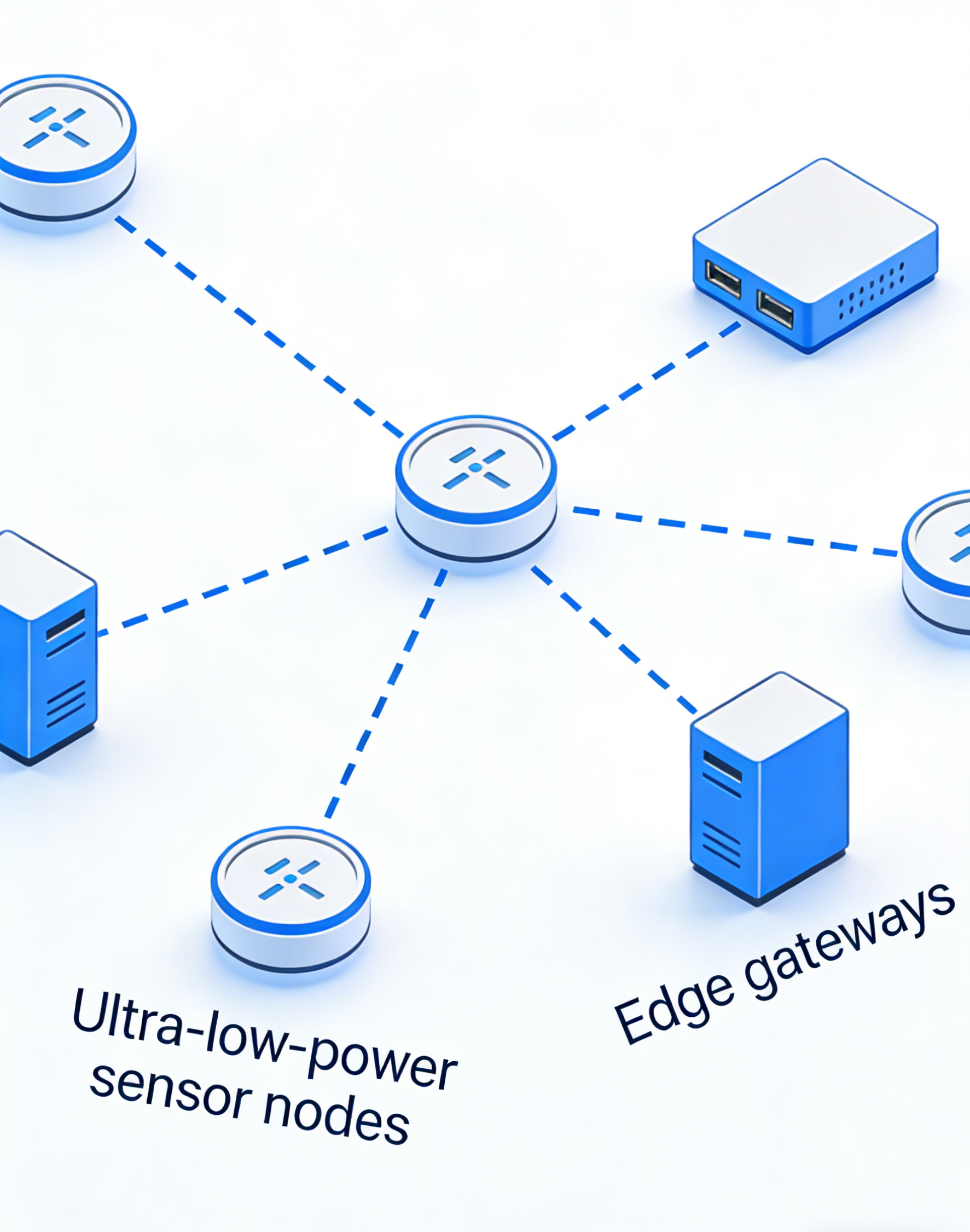
ultra–low-power sensor nodes, edge gateways
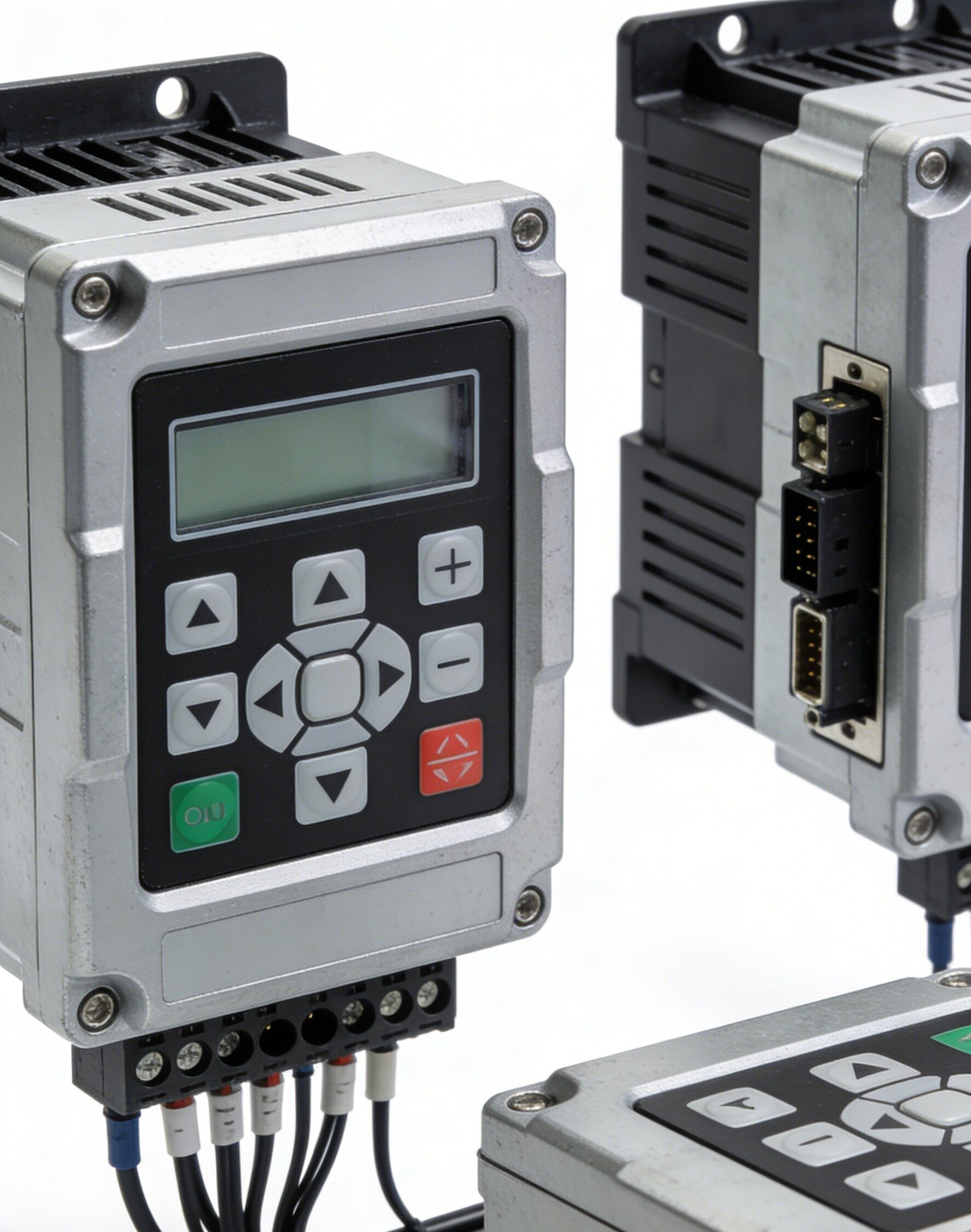
Idustrial controllers

warehousing and logistics
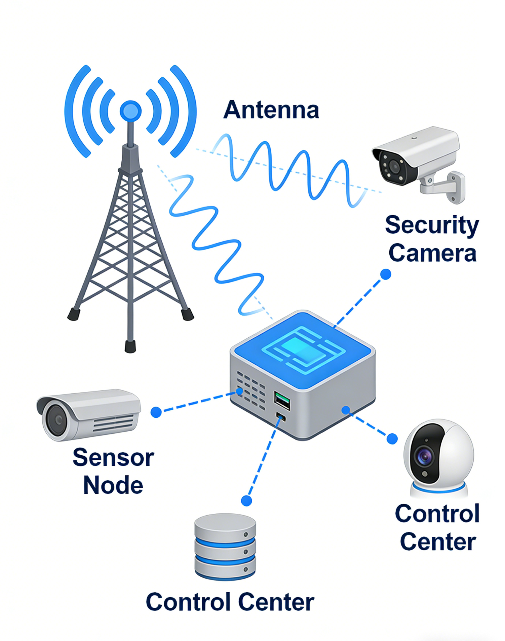
environmental/security
1. Typical antenna bands and radio technologies
Long‑range narrowband LPWAN, to mid/high‑rate cellular and Wi‑Fi backhaul, to high‑accuracy positioning and near‑field interactions.
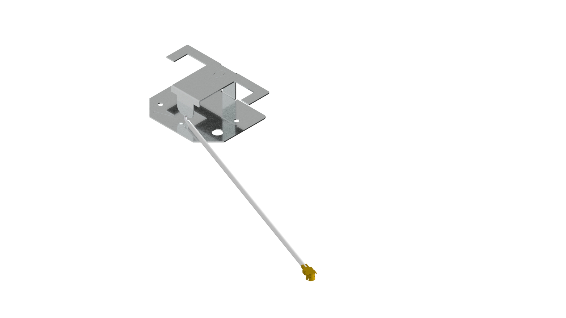
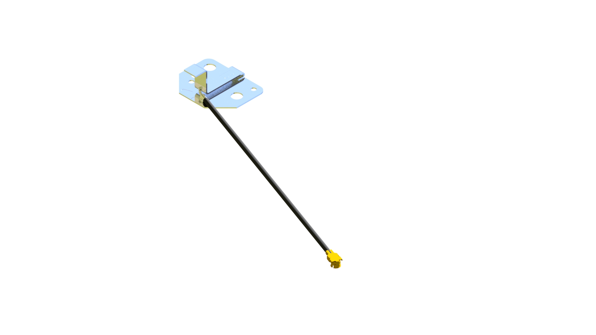
2. Antenna Form Factors and Integration
IoT/IIoT devices range from fingernail‑sized sensors to outdoor cabinets. Antenna selection must balance volume, efficiency, cost, and reliability, while meeting installation and maintenance constraints.
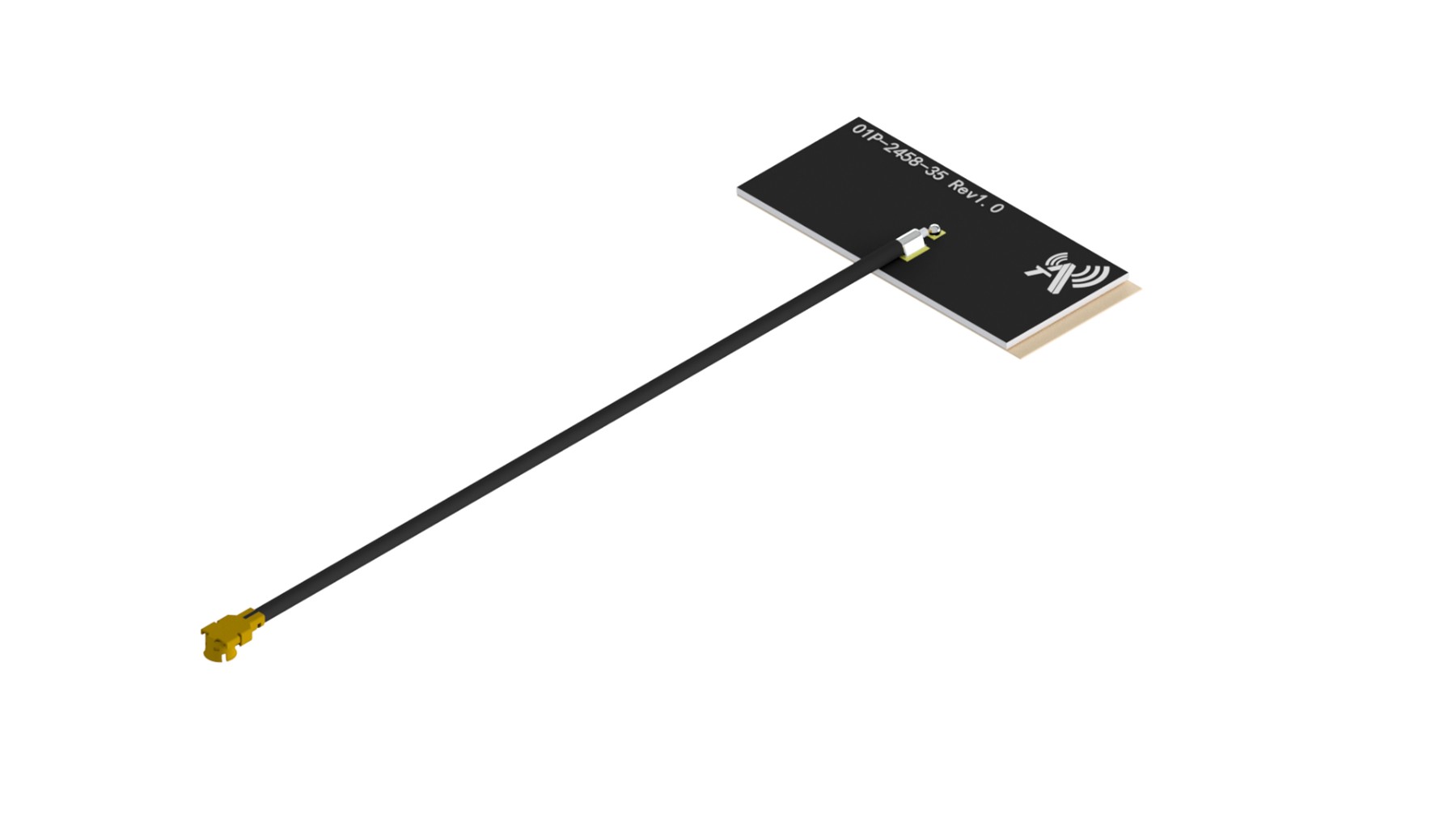
Embedded Antennas
-
- PCB trace/slot/patch/inverted‑F (IFA/PIFA): cost‑effective with good manufacturability; suited to gateways/cameras/controllers
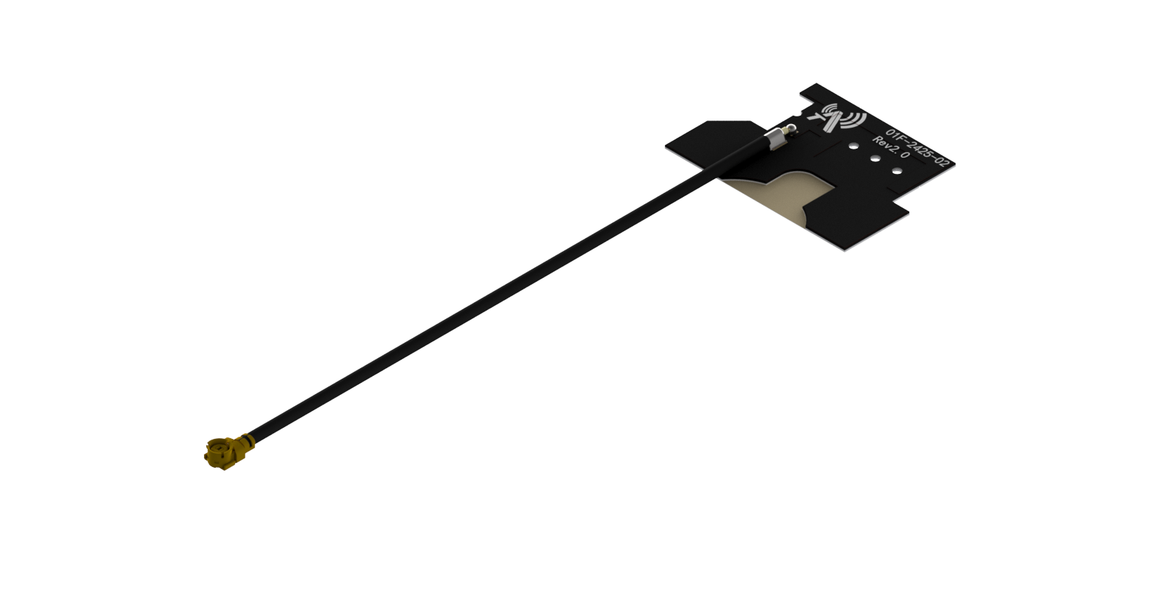
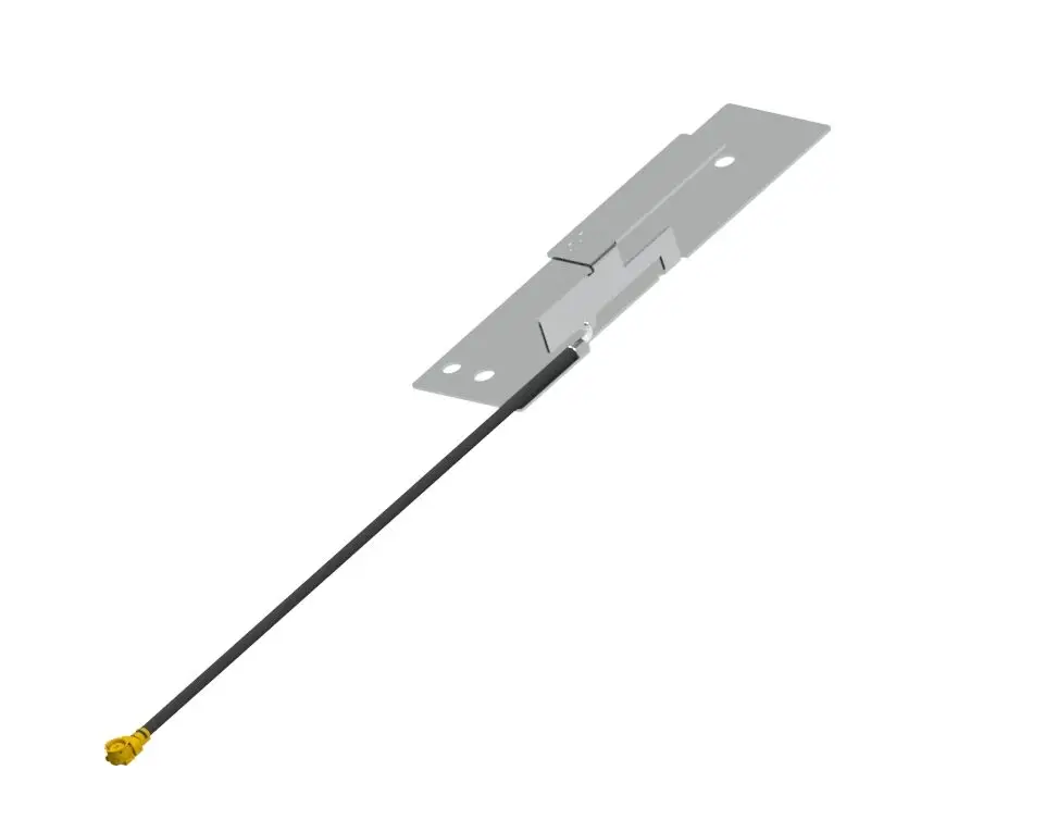
- FPC antennas: conformal to enclosures and metal avoidance; ideal for compact nodes and swappable housings
- LDS/LDP: complex 3D routing for tight spaces, enabling multiband sharing and polarization coupling control
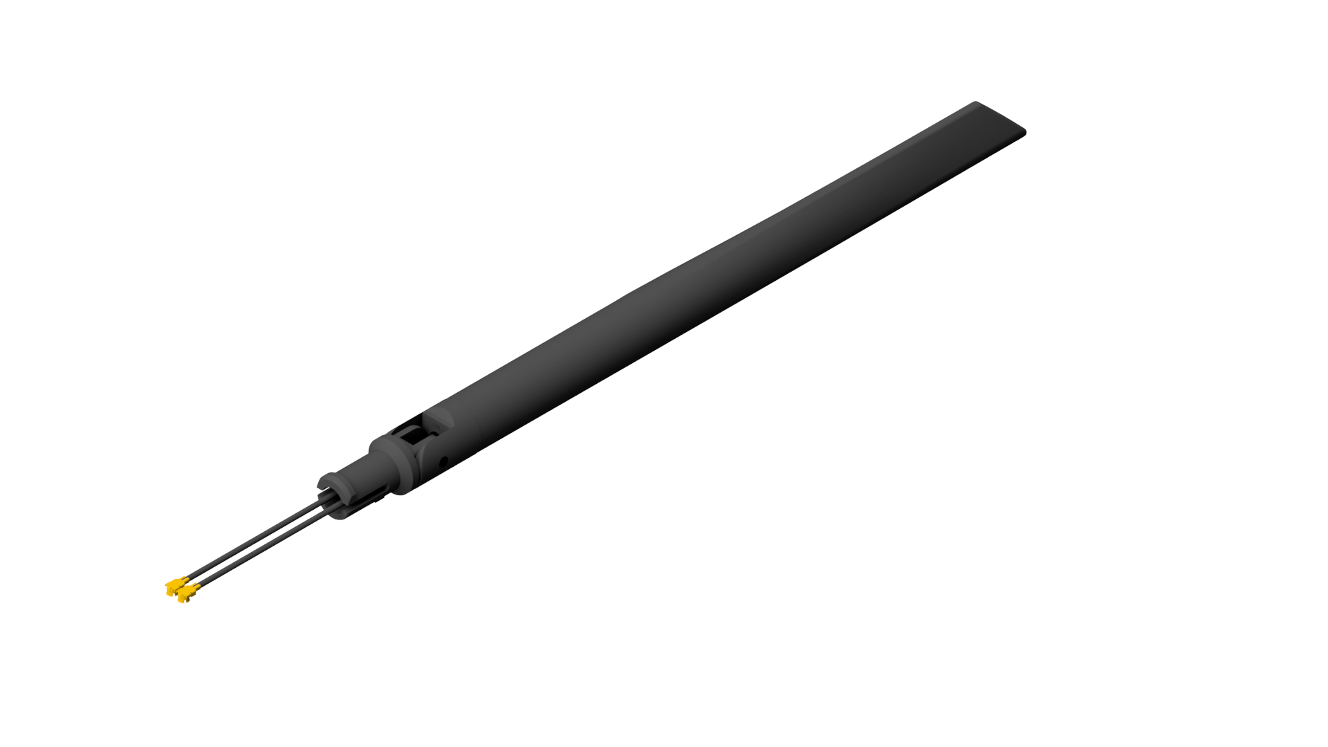
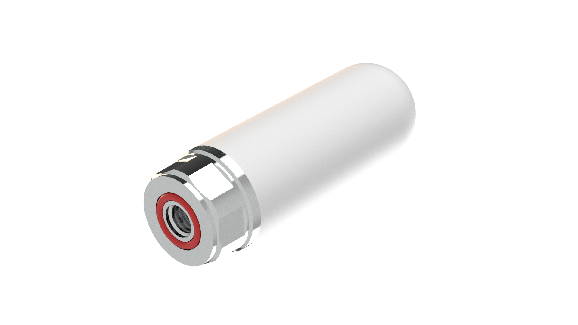
- High‑εr ceramic/miniature patches: for Sub‑GHz/GNSS miniaturization and stability
3. Antenna Design Requirements
Electrical, Mechanical, System, and Compliance
Bands and Bandwidth
- Regional compliance: LoRa 433/470/868/915 MHz variants; UHF RFID 860–960 MHz sub‑banding; Wi‑Fi DFS/EIRP limits; cellular band plans and CA strategy
- Concurrency and co‑location: gateways often run cellular backhaul + Wi‑Fi AP + BLE + GNSS, with added UWB/RTLS or RFID in factories; plan for multi‑radio concurrent operation
Radiation Performance
- Efficiency and gain
- Sub‑GHz (LPWAN/cellular LB): embedded targets ≥20–40%; external omnis ≥40–60%; directional panels commonly 10–15 dBi boresight gain
- 2.4/5/6 GHz: embedded ≥45–65%; external for industrial APs/gateways ≥60–75%
- GNSS: prioritize system G/T and C/N0; passive patch efficiency ≥50% (up‑facing), good axial ratio and XPD
- UWB: target ≥40–60% with group‑delay flatness and phase linearity
- Patterns
- Indoor AP/gateway: azimuthal uniformity within ±3–4 dB; optional electrical downtilt
- Outdoor CPE/backhaul: narrow beams with low sidelobes; windage and elevation mounting tolerances considered
- RTLS: multi‑sector/mixed‑polarization anchors to reduce shadow zones
- Polarization
- Predominantly linear; dual/cross‑pol for harsh multipath and varying device attitude
- GNSS requires RHCP with axial ratio ≤3 dB (main lobe)
Matching and Isolation
- VSWR/return loss: ≤2.0 typical, ≤1.8 in critical sub‑bands; stability under temperature/humidity/assembly and near‑field changes
- Port isolation: MIMO/diversity ≥15–20 dB; cellular ↔ Wi‑Fi/GNSS/UWB/RFID ≥25–35 dB; watch coupling between RFID/NFC and Sub‑GHz
- ECC and correlation: Wi‑Fi MIMO ECC <0.1–0.2; manage channel coherence for RTLS arrays
- OOB and intermodulation: meet 3GPP/IEEE masks; ensure front‑end dynamic range, IP3/IP2, and blocker resilience against industrial interferers (VFDs, welders, motors)
Combining and Filtering Architecture
- Multiplexing/combining: intra‑cellular band combining and inter‑system segregation among cellular/Wi‑Fi/GNSS/UWB; quantify insertion‑loss impact on EIRP/TIS (0.5–1.0 dB is material)
- GNSS front‑end: LNA + SAW/BAW BPF placed near the radiator for low NF and blocker robustness
- UWB: bandpass filtering with group‑delay consistency (critical for ranging accuracy)
- RFID/NFC: tuning compensation and field shaping in metallic environments
Active Front End and RF Path
- Place PA/LNA/switch close to the radiator to reduce feed loss; equalize electrical length/phase for beamforming/RTLS chains
- Power/ground: isolate noisy industrial supplies; filtering and partitioning of AGND/PGND
- ESD/surge: TVS/ESD at antenna ports to IEC 61000‑4‑2/‑4‑4/‑4‑5 levels; account for parasitic C in the matching network
Mechanics and Materials
- Enclosure Dk/Df and coating thickness influence resonance; model early and validate with A/B coupons
- Environmental protection: IP65/67/69K outdoors; UV resistance; salt fog ≥240–720 h; wind load, ice/freeze‑thaw; cable glands and vents to prevent condensation
- Installation: wall/pole/magnetic/ceiling/DIN rail; standardize standoff and metal proximity to control pattern detuning
Compliance and Certification
- Regulatory: FCC/IC/CE/ETSI/SRRC/KC/TELEC/RCM; power density/EIRP/PSD limits, DFS (5 GHz)
- EMC: CISPR 32/EN 55032, EN 301 489, industrial immunity (EN 61000‑6‑2/‑6‑4)
- Exposure: MPE/PD (most IoT); SAR for on‑body/near‑body devices
- Industry norms: intrinsic safety/explosive atmospheres (ATEX/IECEx) for power, oil/gas, mining—antenna and enclosure must co‑comply
4. Antenna Test and Validation Workflow
Laboratory/Anechoic (Passive/Active/OTA)
- Passive characterization
- S‑parameters: S11/S22 and inter‑port isolation S21/S31; in‑band VSWR; near‑field coupling path diagnostics
- Efficiency and gain: 3D far‑field or near‑to‑far transforms; mainlobe/sidelobe/backlobe, HPBW; cross‑pol discrimination (XPD)
- Installation conditions: free‑space vs. wall/pole, proximity to metal/walls, and human presence during maintenance—A/B comparisons
- Active/OTA
- Cellular/Wi‑Fi: TRP/TIS, EIRP/EIS, UDP/TCP throughput, MCS distribution, multi‑client concurrency
- LPWAN: link budget and coverage radius validation; attach success rate; power/latency statistics with repetition schemes
- UWB: ranging error CDF (P50/P95), AoA error, group‑delay flatness/phase linearity
- GNSS: C/N0, TTFF, tracking robustness, blocker/adjacent tolerance under cellular/Wi‑Fi concurrency
- RFID/NFC: field‑strength maps, read range, metal/liquid detuning impact, tag orientation sensitivity
- Environmental coupling and stability
- Temperature/humidity/thermal shock: −20 to +60/70/85°C (consumer/industrial) and up to 85% RH; resonance drift and efficiency decay
- Power noise injection: switching ripple, motor/relay transients impacting RF front‑end
- Mechanical stress: vibration/shock effects on connectors/coax/solder and insertion‑loss drift
Field and System Level Validation
- Coverage and performance maps: RSSI/SNR/throughput heatmaps across plants/warehouses/basements/outdoors; multi‑floor, racking, metal‑dense environments
- Mobility and blockage: AGV/forklift routes and human flow impacts; multipath and shadow fading statistics
- Extreme weather: availability of CPE/cameras/gateways under cold/heat/rain/snow/fog, short‑ and long‑term
- Positioning systems: UWB/GNSS/Bluetooth AoA trajectory error, GDOP sensitivity, and anchor geometry optimization
- Coexistence/interference: WLAN–BLE coexistence, LPWAN vs. UHF RFID co‑presence, microwave backhaul influence on 2.4/5 GHz
Reliability and Durability
- Environmental: UV aging; salt fog (IEC 60068‑2‑11); damp‑heat cycling; thermal shock (IEC 60068‑2‑14); freeze–thaw, rain/condensation
- Mechanical: vibration/shock (IEC 60068‑2‑6/‑2‑27); drop (transport/installation simulation)
- Sealing: IP re‑validation (IP65/67/69K); vent permeability vs. water ingress; performance drift due to water films/dust accretion
- Interconnects and cabling: coax/feeder/terminal mating life, tensile strength, bend radius, strain relief; keying and locking
- Long‑term drift: 30/90/180‑day tracking; in‑service self‑monitoring (VSWR anomalies, RSSI outliers) and remote alarms
5. Engineering Practices and DfX Recommendations
Layout and Isolation
- Prioritize spatial/polarization diversity for MIMO; layer‑separate 2.4/5/6 GHz radiators to avoid boresight overlap; physically isolate Sub‑GHz from high bands
- Maintain continuous low‑impedance ground returns; avoid long narrow ground necks; equalize potentials across metalwork to suppress common‑mode and unintended dipoles
- In metal‑dense sites, provide decoupling gaps, absorbers, and common‑mode chokes
Change Control and Mass Production
- RF re‑validation gate for changes to enclosure resin, coating thickness, stiffeners, shield location, cable routing
- SPC in production: Cpk targets and AQL for S11, efficiency, isolation, EIRP, TRP/TIS, C/N0; rapid near‑field/OTA screening on the line
- MES traceability: coax length/bend radius, connector torque, material lots, tuning settings
6. Reference Target Metrics
Adjust by Product Class and Scenario
7. Test and Certification Checklist
For Program Gate Reviews
- RF/Antenna: S‑parameters, efficiency, 3D patterns, polarization, isolation, ECC, TRP/TIS/EIRP/EIS, throughput/MCS, UWB ranging/AoA, GNSS C/N0/TTFF, RFID/NFC field strength/read range
- Environmental/Reliability: temp‑humidity cycling, thermal shock, vibration/shock, drop, salt fog, UV, freeze–thaw/condensation, IP rating
- EMC/Regulatory: CISPR 32, EN 301 489, EN 61000‑6‑2/‑6‑4, FCC/IC/CE/SRRC/KC/TELEC/RCM, DFS (5 GHz)
- Coexistence/Blocking: cellular UL and microwave backhaul impact on GNSS/UWB/WLAN/LPWAN; WLAN–BLE coexistence; Sub‑GHz with UHF RFID co‑channel/adjacent interference; IMD/spurious
- Field: coverage/capacity across factories/warehouses/campuses/basements/outdoors; AGV/AMR mobility stability; metal‑dense multipath scenarios
- Mass Production: SPC/Cpk, AQL sampling, in‑line rapid near‑field/OTA, MES traceability and failure forensics
Ralated Antenna