

AOC
A Technical Overview of Antenna Design
Antenna design for consumer electronics is a multi-standard, multi-constraint systems engineering exercise that must balance minimal form factor, complex materials, and high concurrency. By defining spectrum and service KPIs at project inception; selecting manufacturable structures and processes (FPC/LDS/conformal slots/patches); pairing with appropriate combining and filtering architectures, PA/LNA placement, and algorithmic co-design (beamforming, power control, coexistence management); and instituting a layered validation and mass-production consistency framework from passive to active and lab to field, products can achieve superior coverage, capacity, and user experience while reducing certification and ramp risks and accelerating time‑to‑market. Provide specific device form factor, dimensional constraints, target spectra, and cost bracket to receive a tailored antenna topology, initial matching values, combining/filtering BOM, and a detailed test matrix.
Key Application Scenarios
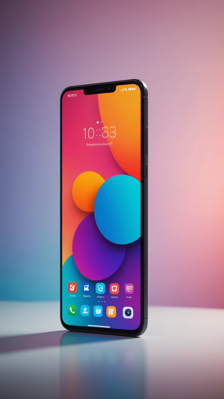
smartphones
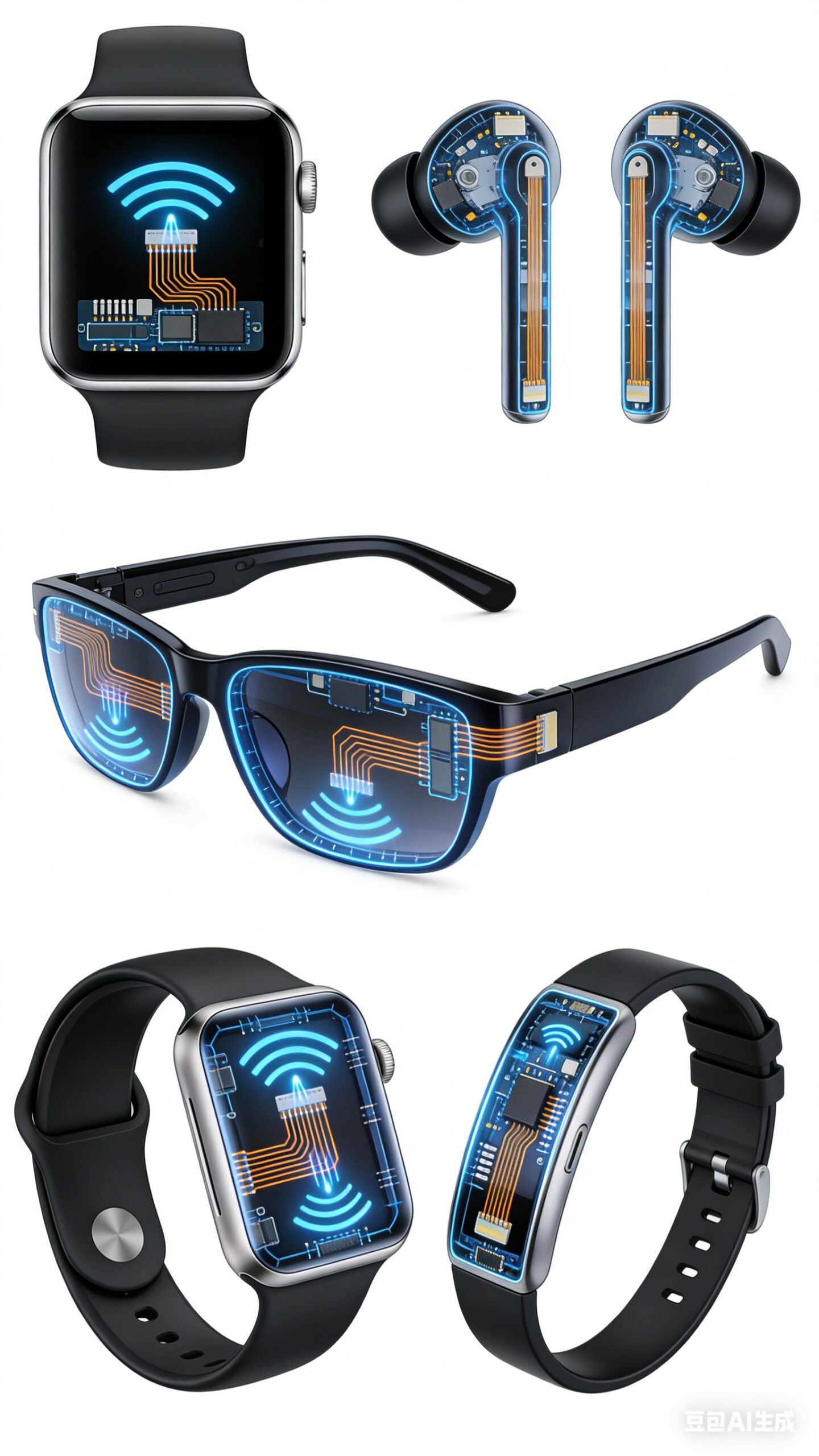
Wearables
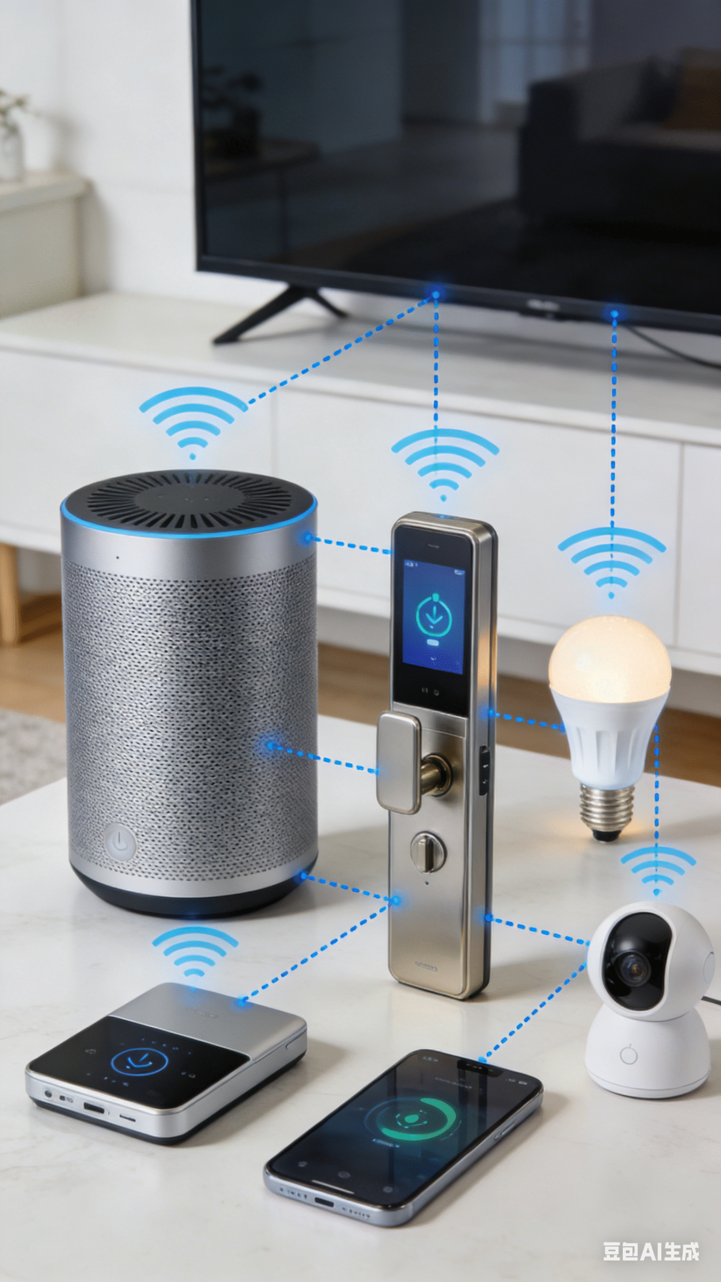
Smart Home
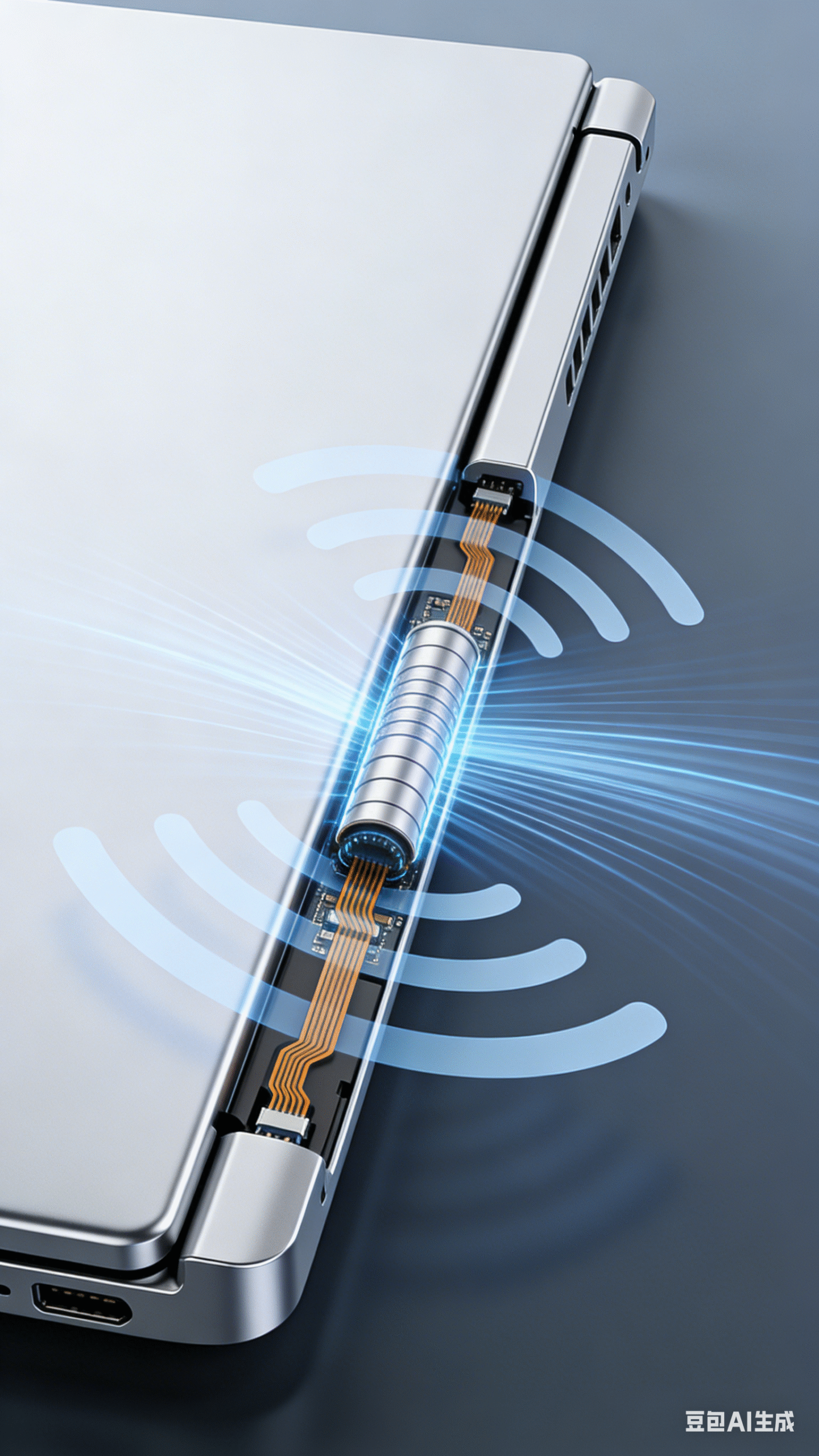
notebooks
1. Typical antenna bands and radio technologies
Antenna design must integrate multi-standard, multi-antenna systems within highly constrained volumes to deliver high data rates, low latency, low power, and superior user experience.
2. Antenna Form Factors and Integration
Consumer devices impose extreme spatial constraints and frequent industrial design changes. Antennas are typically co-designed with the chassis using metal frames, bezels, glass/plastic back covers, and FPC/LDS processes for conformal, invisible integration.
Smartphones/Tablets/Notebooks
-
- IFA/PIFA/multi-branch inverted‑F: leverage metal mid‑frames/antenna split gaps to realize multiband operation; use slots, coupling fingers, and matching networks to cover low bands (600–960 MHz) and high bands (1.7–2.7 GHz)
- LDS/LDP antennas: directly patterned on plastic carriers or back covers for complex 3D routing
- Glass/ceramic‑coupled radiators: dielectric loading to reduce electrical size
- Wi‑Fi/BT/UWB arrays: distributed at top/side/back to improve diversity and spatial streams
- mmWave AiP modules: phased or switched diversity subarrays placed around the perimeter
Wearables (Watches/Bands/Glasses/Earbuds)
-
- Flexible FPC loop/helix: embedded in straps/frames; optimized for body loading and SAR
- Ceramic/high‑εr patches: for GNSS and compact 2.4/5 GHz radiators
- Earbuds: slot/printed antennas in metal cavities or FPC in stems; optimized for grip/occlusion robustness and spatial audio sync
- Glasses/AR headsets: temple FPC, frame slots, arrayed UWB
3. Antenna Design Requirements (Electrical, Mechanical, and System-Level)
Bands and Bandwidth
- Cellular: cover global priority bands with carrier aggregation (CA) and EN‑DC/NR‑DC; employ multi-branch or wideband strategies to realize low bands (600/700/800/900 MHz) and high bands (1.8–2.7 GHz).
- WLAN/WPAN: continuous coverage at 2.4/5/6 GHz; Wi‑Fi 7 requires wider channels and MLO; UWB commonly targets 6.5–8.5 GHz operational windows.
- GNSS: L1 baseline, L5/dual-frequency for enhanced multipath immunity; optional active solutions with LNA/SAW.
- NFC: 13.56 MHz; match to system equivalent impedance; co-optimize coupling coefficient and read range.
Radiation Performance and UX
- Gain and efficiency: embedded phone/tablet antennas typically target ≥35–50% (LB) and ≥50–70% (HB/Wi‑Fi) radiation efficiency; notebooks/routers can exceed these. UWB efficiency is constrained by form factor and filtering; target ≥40–60%.
- Patterns: accommodate grip, head proximity, and back cover proximity; routers/speakers emphasize azimuthal uniformity and controlled downtilt.
- Polarization: predominantly linear; consider polarization diversity for UWB/positioning; GNSS requires RHCP with axial ratio ≤3 dB (main lobe)
Matching, Isolation, and Coexistence
- VSWR/return loss: ≤2.0 typical, ≤1.8 in critical sub‑bands; maintain stability under temperature, assembly, and near-field perturbations (grip/desk/enclosure changes).
- Port isolation: MIMO ≥15–20 dB; cellular vs. Wi‑Fi/UWB/NFC ≥25–30 dB. Extremely compact wearables often require structural isolation plus filtering.
- ECC/correlation: ECC <0.2 for MIMO (≤0.1 for high-end Wi‑Fi); prioritize spatial and polarization diversity.
- Filtering and nonlinearity: OOB suppression for GNSS/UWB, adjacent-channel and intermodulation management for cellular; account for ESD diode parasitics on bandwidth/efficiency.
Mechanics, Materials, and Environment
- Enclosure Dk/Df control: glass/ceramic/plastic differences cause resonance shifts; any coating/plating/silkscreen thickness change mandates RF revalidation.
- Grounding/shielding: continuous low-impedance grounds; avoid narrow ground necks; equalize shields and metal structures to suppress common-mode radiation and unintended dipoles.
- Body loading and SAR: comply with SAR/PD/MPE via pattern shaping, cavities/magnetic sheets, and power control.
- Protection: wearables require sweat/water ingress protection (IPX7/8) and corrosion resistance; earbuds/speakers must recover performance post droplets/condensation.
4. Antenna Performance Test and Validation Workflow
Laboratory/Anechoic Testing
-
Passive characterization
- S‑parameters: S11 and multiport isolation S21/S31; examine out-of-band resonances and parasitic modes in low bands.
- Efficiency and gain: 3D OTA or near-to-far-field transforms; quantify main lobe, sidelobes, and cross‑polarization discrimination.
- Patterns under user scenarios: free-space vs. single-hand/double-hand/head‑load/desktop/wall‑mount; for UWB, assess group delay flatness and phase linearity (AoA/ToF fidelity).
- Active/system metrics
- TRP/TIS (cellular/Wi‑Fi), EIRP/EIS, peak and P95 throughput, MCS distribution, link robustness.
- MU‑MIMO/beamforming: spatial stream retention and beam switch latency under multi-client load.
- UWB: ranging error (P50/P95), clock drift impact, NLOS/body‑block fading model validation.
- NFC: read range, coupling factor, metal detuning effects, field strength distribution, and EMC compatibility.
- Environmental coupling
- Temperature/humidity/thermal shock: −20 to +60/70°C (consumer) or wider; track frequency shift, efficiency variation, and matching compensation strategies.
- Assembly/material tolerances: statistical impact of cover, adhesives, foams, magnetic sheets on performance.
Field Testing and UX Evaluation
- Coverage and roaming: indoor/outdoor RSSI/SNR heatmaps; multi-floor penetration; coverage under motion/pose for wearables.
- Capacity and concurrency: router/speaker/camera throughput/packet loss with many clients; mesh stability in smart-home networks
- mmWave: beam switch success rate under grip/occlusion; fallback latency to Sub‑6 and perceived experience.
EMC/EMI and Coexistence
- Emissions: CISPR 32/EN 55032; Wi‑Fi/BLE coexistence in 2.4 GHz with TDM coordination and interference avoidance.
- Immunity: EFT/Surge/ESD, CS/RS; verify port isolation and filter effectiveness.
- Co-location: cellular–Wi‑Fi, Wi‑Fi–UWB, UWB–GNSS, NFC–cellular interference; intermodulation (IMD) detection and mitigation.
Reliability and Durability
- Mechanical/environmental: drop, sweat, salt fog, UV, vibration; accelerated corrosion and seal life for earbuds/watches.
- Protection and recovery: performance recovery after splash/condensation/freeze–thaw; connector/pogo/FFC endurance.
- Long-term stability: 30/90/180‑day drift tracking; self-diagnostics (VSWR/thermal anomalies) and power limiting policies.
5. Design and Integration Best Practices
- Layout and isolation
- Ensure spatial and polarization diversity for MIMO; layer-separate 2.4/5/6 GHz radiators to avoid boresight overlap.
- For cellular low bands, maintain continuous ground reference and manage frame slots/bridges with controlled RLC equivalents.
- Matching and tuning
- Reserve π/T matching pads and shunt jumpers; apply DOE to quantify sensitivity to assembly/material variances (frequency shift, efficiency).
- When introducing absorbers/magnetic sheets, conduct A/B small-sample studies and establish frequency–thickness calibration curves.
- Feedlines and interconnect
- Prefer low-loss coax/FFC; avoid sharp 90° bends; manage per-chain electrical length and phase consistency (critical for Wi‑Fi beamforming).
- Active front-end and algorithm co-design
- PA power control linked to SAR/MPE; receiver LNA gain switching coordinated with interference detection (Wi‑Fi/BLE concurrency).
- UWB ranging calibration for antenna group delay and AoA direction finding.
- Change control for mechanics/materials
- Any changes to plastics, coatings, metal parts, foams, adhesives, or boss locations trigger RF revalidation with sign-off.
- Mass-production consistency and traceability
- Establish SPC on key KPIs (S11, efficiency, isolation, TRP/TIS); define sampling/AQL; use fast near-field scans on the line for pre-screening.
6. Reference Target Metrics
Smartphones (Sub 6; 4×4 MIMO @ 5/6 GHz; 2×2 @ 2.4 GHz)
-
- Port isolation: ≥18–20 dB; ECC <0.1
- Efficiency: LB ≥35–45%, HB ≥55–70%; median grip attenuation ≤6–8 dB
- GNSS: axial ratio ≤3 dB (main lobe); active NF ≤1.5–2.0 dB
- UWB: 6.5–8.5 GHz efficiency ≥45–60%; system group delay ripple ≤±0.5 ns
- SAR: compliant via coordinated power/beam/scheduler control
7. Test and Certification Checklist
For Gate Reviews
- RF/Antenna: S‑parameters, efficiency, 3D patterns, polarization, isolation, ECC, TRP/TIS/EIRP/EIS, throughput/MCS distribution, UWB ranging error, NFC field strength and read range
- Environmental/Reliability: temperature–humidity/thermal shock/drop/vibration/sweat/salt fog/UV/IP; connector/pogo life
- EMC/Regulatory: CISPR 32, EN 301 489, FCC/IC/CE/TELEC/KC/SRRC; DFS/radar (5 GHz); SAR/MPE/PD
- Field UX: throughput/latency under grip/wear scenarios; multi-device coexistence; mesh/multi-room coverage
Antennas for AOC application
© 2026 All Rights Reserved.