

AOV (Automotive Communication Systems)
AOV
A Technical Overview of Antenna Design
Automotive antenna engineering is a multidisciplinary systems effort that must balance concurrent multi‑radio operation, harsh environmental constraints, complex vehicle electromagnetics, and regulation. By defining spectrum and service KPIs early; architecting appropriate combining/filtering and active front‑ends; optimizing vehicle coupling and installation; enforcing phase consistency and port isolation; and instituting a layered validation flow from passive to vehicle‑road tests with SPC in production, programs can markedly improve cellular coverage, V2X reliability, GNSS accuracy, and in‑cabin connectivity, while reducing in‑service and regulatory risk and accelerating SOP. Provide platform details, available shark‑fin volume, target spectra/regions, and feature set (UWB/RTK/6E/NR‑V2X) to receive a tailored antenna topology, combiner/filter BOM, insertion‑loss budget, and a comprehensive test matrix.
Key Application Scenarios
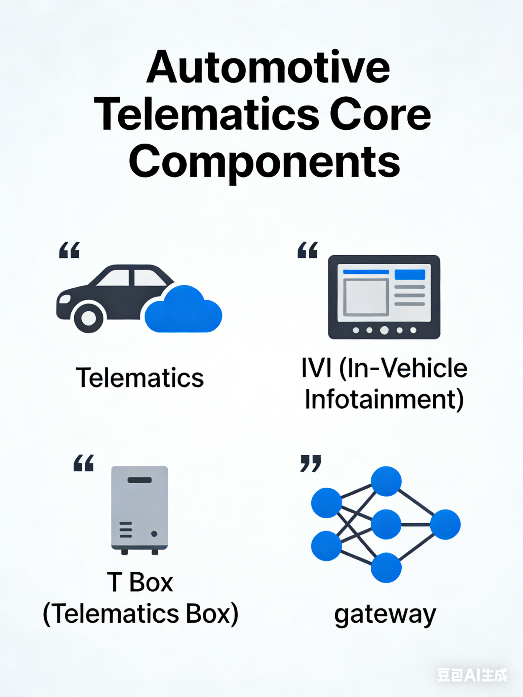
Telematics/IVI/T Box/gateway
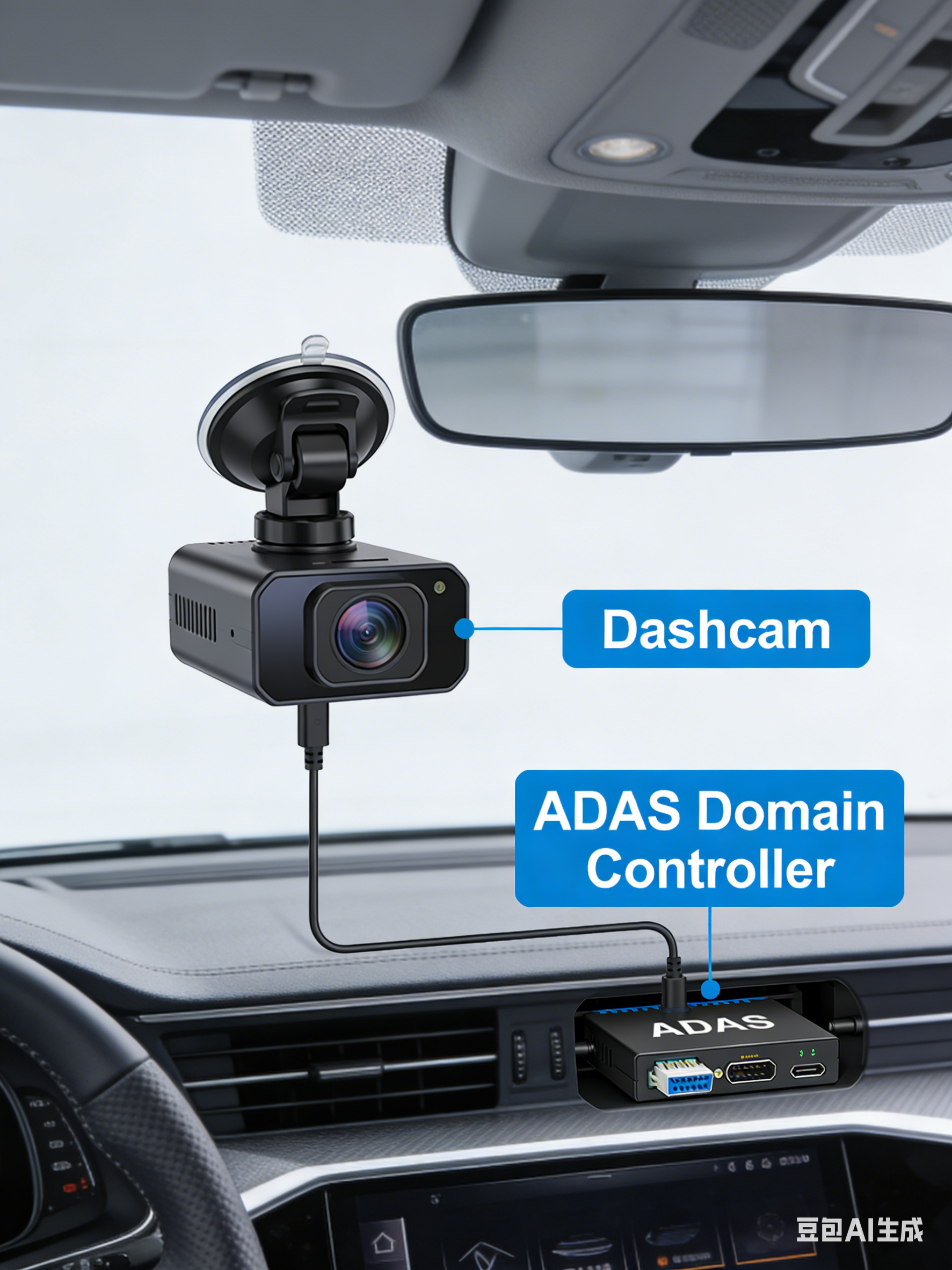
Dashcam and ADAS domain controllers
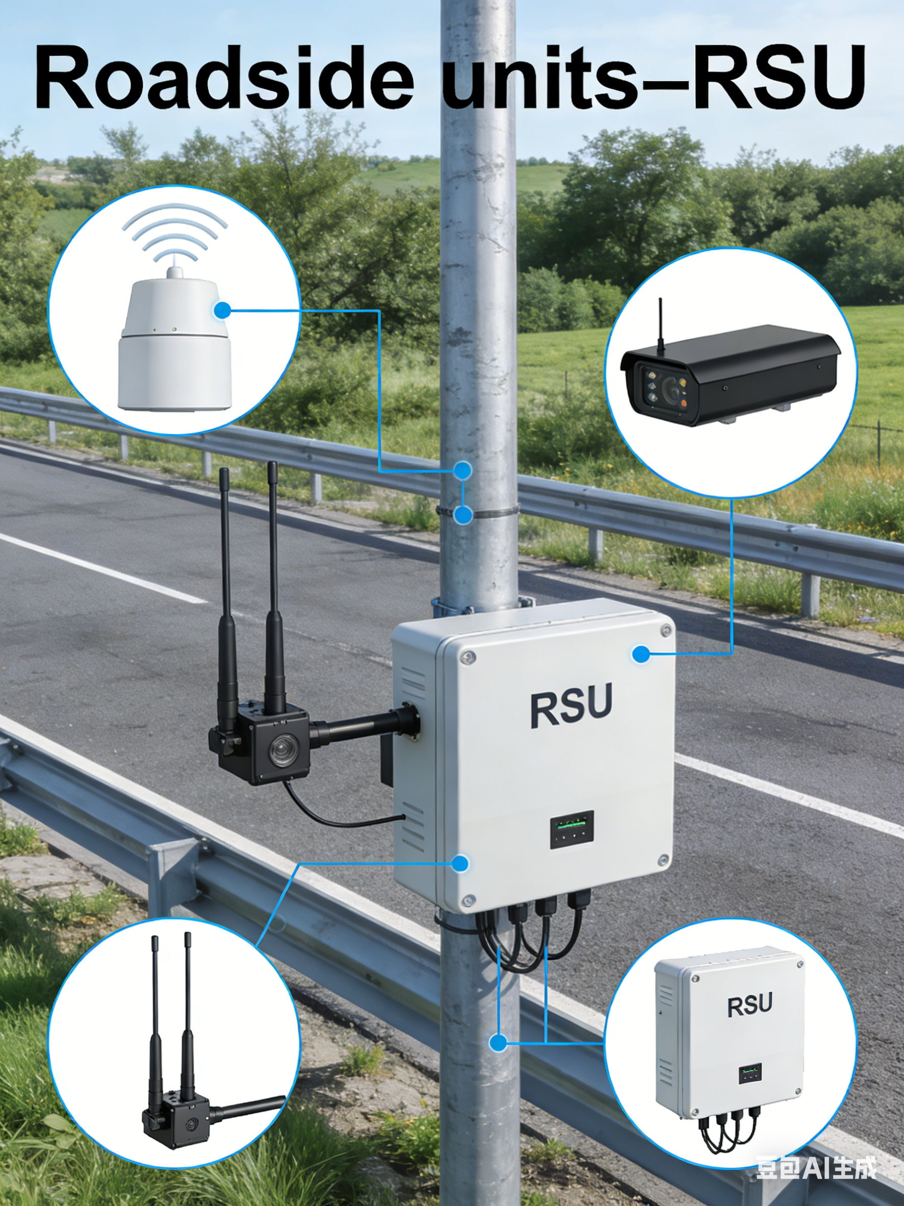
Roadside units—RSU
1. Typical antenna bands and radio technologies
Automotive communication systems (Telematics/IVI/T‑Box/gateway, dashcam and ADAS domain controllers, roadside units—RSU) must deliver highly reliable, concurrent multi‑radio connectivity under harsh environments. Typical functions include cellular (4G/5G), C‑V2X/DSRC, GNSS timing and positioning, Wi‑Fi hotspot and rear‑seat entertainment, Bluetooth/BLE, UWB digital keys, NFC, satellite and terrestrial broadcast (AM/FM/DAB/SXM), and optional satellite communications (Ku/Ka/L).
Cellular and V2X
-
- 4G LTE FDD/TDD: common bands at 700/800/900/1800/2100/2600 MHz with CA/VoLTE
- 5G NR Sub‑6: n1/n3/n7/n8/n20/n28/n38/n40/n41/n77/n78; optional FR2/mmWave (n257/n258/n260) on select platforms
- C‑V2X PC5 (LTE‑V2X Rel‑14/15, NR‑V2X Rel‑16+): 5.9 GHz (e.g., 5.855–5.925 or 5.905–5.925 GHz by region); or DSRC 802.11p/ITS‑G5 (5.8/5.9 GHz)
WLAN/WPAN and Proximity
-
- Wi‑Fi 4/5/6/6E/7: 2.4, 5, and 6 GHz for in‑vehicle hotspots, rear‑seat entertainment, and OTA updates
- Bluetooth/BLE: 2.4 GHz (pairing, phone integration, peripherals)
- UWB: 6.5–8.5 GHz (CCC Digital Key ranging/AoA)
- NFC: 13.56 MHz (door handle/center console for tap‑to‑start/pairing)
2. Antenna Form Factors and Integration
Automotive antennas typically combine “shark‑fin combo” modules with glass/vehicle‑body hidden antennas and localized near‑end antennas, balancing aerodynamics, styling, NVH, and vehicle‑level EMC.
Shark Fin/Combo Roof Antenna
-
- Multistandard integration in one radome: cellular (2×2/4×4), GNSS (active/passive), AM/FM/DAB, SXM, C‑V2X, Wi‑Fi, UWB, etc.
- Structure: ABS/PC radome with UV coating; internal PCB/FPC/patch/slot/wire elements referenced to a metal ground plate for conformal coupling
- Benefits: reduced in‑cabin interference, open sky view for GNSS/SXM, serviceable module
3. Antenna Design Requirements
Electrical, Mechanical, System, and Regulatory
Bands and Bandwidth
- Cellular and C‑V2X: cover target market bands and 5.9 GHz ITS; account for SDARS/SXM and DAB regional variants; full 6 GHz sub‑bands for Wi‑Fi 6E/7
- Concurrent multi‑radio operation: cellular + Wi‑Fi hotspot + GNSS + V2X commonly run simultaneously; mandate combining/filtering and isolation strategy
Radiation Performance
- Gain/Efficiency: with roof‑mount ground plane, cellular HB efficiency ≥50–60%, LB ≥30–45%; Wi‑Fi ≥55–65%; GNSS passive ≥50% efficiency (system G/T is primary figure of merit); SXM requires adequate gain over satellite elevation angles
- Patterns: GNSS needs uniform upper‑hemisphere coverage with good XPD; cellular/Wi‑Fi require azimuthal coverage with controlled elevation HPBW; V2X emphasizes near‑horizon mainlobe and sidelobe suppression to mitigate interference
- Polarization: linear for cellular/Wi‑Fi; RHCP for GNSS with ≤3 dB axial ratio; SXM/broadcast per system specs; UWB multi‑site and mixed polarization for robustness
Matching and Isolation
- VSWR: ≤2.0 typical, ≤1.8 in critical sub‑bands; stable under −40 to +85/95°C, humidity, aging, and water‑film conditions
- Port isolation: MIMO ≥18–22 dB; cellular ↔ Wi‑Fi/GNSS/V2X ≥25–35 dB; avoid strong coupling between exterior and interior antennas
- MIMO correlation/ECC: cellular 2×2/4×4 and Wi‑Fi 2×2/4×4 with ECC <0.2/<0.1; reduce path correlation via spatial, polarization, and angular diversity
Combining and Filtering Architecture
- Multicouplers/duplexers: intra‑cellular band combining and cellular–V2X/Wi‑Fi segregation; OOB suppression to meet 3GPP/IEEE masks
- GNSS front‑end: LNA plus SAW/BAW BPF, high IP3/blocker resilience; place near the antenna to minimize NF
- UWB: bandpass filtering and group‑delay consistency; digital key performance is sensitive to GD ripple and phase linearity
Active Front End and RF Path
- PA/LNA placement: minimize physical length to radiators; control feedline loss and inter‑chain phase skew
- Phase/amplitude consistency: required for Wi‑Fi MIMO/beamforming and UWB AoA; support factory calibration and in‑field self‑cal
- TCU/gateway co‑location: mitigate mutual coupling and noise with isolation and shielding
Mechanics and Materials
- Radome dielectric control (Dk/Df): RF‑transparent materials (ASA/PC/PP+GF), model frequency shifts due to coatings/clearcoats
- Sealing: IP67/69K with water/dust ingress protection, salt fog (≥480–720 h premium), anti‑icing; drainage paths and breathable membranes
- Reliability: vibration (ISO 16750), thermal cycling/shock (−40 to +85/95°C), UV, stone impact, car‑wash loads
- Vehicle coupling: co‑simulation/tuning with sunroof/roof rack/metal base; avoidance strategies for glass heater lines and printed antenna traces
Regulatory and Regional Variants
- Wireless: FCC/IC/CE/ETSI/SRRC/KC/TELEC; V2X channelization and EIRP limits by region; DFS for 5 GHz Wi‑Fi
- Automotive EMC: AEC‑Q, ISO 16750; immunity per ISO 11452; emissions per CISPR 25
- Exposure/safety: MPE/occupant exposure; cabin power density assessment; proximity limits for keys/children
4. Antenna Test and Validation Workflow
Laboratory/Anechoic (Passive/Active/OTA)
- Passive
- S‑parameters: S11 and isolation S21/S31; frequency drift under wide temp/humidity and condensation/water‑film; ground plane effects on resonance
- Patterns/gain: 3D OTA or near‑to‑far transforms; GNSS RHCP axial ratio and XPD; V2X azimuthal patterns and sidelobes
- Efficiency: total radiated efficiency including feed/combiner; compare bare module vs. roof‑integrated assembly (A/B)
- Active/System
- Cellular/Wi‑Fi: TRP/TIS, EIRP/EIS, UDP/TCP throughput, MCS distribution, multi‑client concurrency
- GNSS: C/N0, TTFF, tracking stability, blocking/adjacent interference tolerance (cellular UL at max power, Wi‑Fi transmissions)
- V2X: PDR/latency/range, broadcast reliability under DCC, multi‑vehicle interference scenarios
- UWB: ranging error (P50/P95), AoA error, in/out‑of‑cabin NLOS/body blockage; GDOP sensitivity to anchor geometry
- NFC: read range; detuning with metal/rain/ice accretion; false‑trigger assessment
- Environmental Coupling
- Temperature/humidity/thermal shock: −40 to +85/95°C, up to 90% RH; resonance drift, efficiency degradation, matching compensation
- Water film/rain/ice: VSWR/efficiency changes with surface films; define recovery criteria after defog/de‑ice
- Vibration + temperature: monitor connector/solder/coax wear and insertion‑loss drift
Vehicle Level Field and Road Testing
- Coverage/performance maps: RSRP/RSRQ/SINR/throughput in urban/highway/mountain/tunnel; inter‑operator and inter‑band handovers
- GNSS and high‑precision positioning: urban canyon/tree canopy/flyover/tunnel transitions; RTK fix rate and error CDFs; multi‑constellation/multi‑frequency convergence
- V2X: V2V/V2I (RSU) range, PDR, latency; dense traffic and high‑speed head‑on conditions; performance under rain/snow/fog and EM‑intense sites (toll plazas/substations)
- Wi‑Fi hotspot: multi‑user cabin throughput, spatial uniformity, UL/DL symmetry; parking garage/community coverage
- UWB/NFC: door/trunk access success rates with pocket/bag, wet hands/rain; relay/MITM resistance tests
EMC/EMI and Coexistence
- Automotive EMC: CISPR 25 (Class 3/5 targets), ISO 11452‑2 (radiated immunity), ‑4 (BCI), ‑5 (CI), ‑9 (portable transmitter immunity); vehicle‑level validation
- Co‑location interference: cellular UL at max power blocking GNSS (L1/L5), UWB, NFC, SXM; V2X adjacency with 5 GHz/6 GHz Wi‑Fi
- Intermodulation/nonlinearity: intra‑shark‑fin IMD, active combiner IP2/IP3, third‑order products
Reliability and Durability
- Mechanical: random/sine vibration, shock, transport drops, stone‑chipping, car‑wash brush contact
- Environmental: salt fog (IEC 60068‑2‑11, ≥480–720 h), UV aging, temp‑humidity cycling, freeze‑thaw, thermal shock
- Sealing and breathing: vent membrane reliability; leak risk under pressure/thermal cycling and recovery behavior
- Cables/connectors: mating life, corrosion resistance, clamp force, ground‑spring integrity
- Long‑term drift: in‑fleet monitoring (30/90/180 days) and remote diagnostics (VSWR anomalies, C/N0 degradation alarms)
5. Engineering Practices and DfX Recommendations
Layout and Isolation
- Internal compartmentalization within the shark‑fin; orthogonal orientation and separation of critical ports; continuous ground with no narrow necks
- Exterior vs. interior domain separation: GNSS/SXM/cellular primary arrays on the roof; Wi‑Fi/BLE cabin antennas inside; distributed UWB nodes
- Physical and filtering isolation between 5.9 GHz V2X and 5/6 GHz Wi‑Fi; use metallic partitions and absorbers where needed
Tuning and Tolerances
- Reserve π/T matching and jumpers; DOE to quantify sensitivity of resonance/efficiency to temperature, assembly, and lot‑to‑lot variances
- Change‑control checklist requiring RF re‑validation: radome material, coating thickness, baseplate deformation, heater‑wire routing, roof‑rack geometry
6. Reference Target Metrics
Adapt per Vehicle Segment and Feature Set
7. Test and Certification Checklist
For Program Gate Reviews
- RF/Antenna: S‑parameters, isolation, efficiency, 3D patterns, GNSS axial ratio and C/N0, TRP/TIS/EIRP/EIS, throughput/MCS, V2X PDR/latency, UWB ranging/AoA error, NFC field strength/read range
- Environmental/Reliability: temp‑humidity cycling, thermal shock, vibration/shock, salt fog/UV, freeze‑thaw, rain/ice films, IP67/69K, stone impact/car‑wash
- EMC/Automotive: CISPR 25, ISO 11452‑2/4/5/9, ISO 7637 (transients), ISO 10605 (ESD), regional RF regs (FCC/ETSI/SRRC/KC/TELEC), and V2X‑specific rules
- Coexistence/Blocking: cellular max‑UL impact on GNSS/UWB/NFC/SXM; Wi‑Fi adjacency with V2X; IMD/spurious checks
- Field/Road: urban/highway/mountain/tunnel/garage across seasons/weather; in‑cabin hotspot QoE
- Mass Production: SPC/Cpk, sampling/AQL, in‑line rapid OTA/near‑field scans, MES traceability